Home | Search | Help | Comments
Home | Search | Help | Comments
 Expand/collapse
all sections on this page
Note:
Click on the triangle icon above to expand or collapse all sections.
Before printing this page, either use this “expand all” feature, or
expand only the sections for which you want to print more detail.
Compactor End of Stroke Sensor Calibration | Roller Closed Sensor Calibration | Roller Preload Procedure | Traction Test | Twisted Backbone Procedure
Roller Preload Procedure
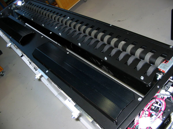
- Remove the arborite and flexible skirt from the top of the SSR unit.
- Unscrew the preload screw from the fixed backbone until it is slack.
- Unscrew the preload screw from the floating backbone until it is slack.
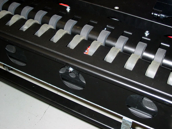
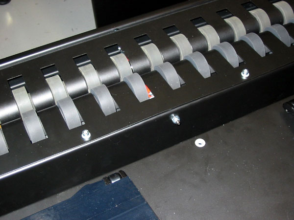
- Remove the batwings from the moving roller backbone.
- Turn each screw in until contact is made, without any preload.
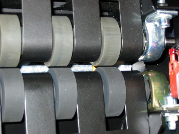
- Hold the center section of the rollers together by hand (make sure the pneumatics are disconnected). Screw in each of the preload screws equally, until a gap of 1.5 to 2.0 mm is achieved at the outermost wheels.
- Connect the pneumatics and close the rollers. Use the air cylinders to force the backbones together.
- Perform a traction test.
- When the traction is uniform along the roller length, tighten the locknuts on the preload adjustment screws while holding the set screws in place with an Allen key.
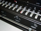
- Re-install the batwings, skirt, and arborite.
This procedure only applies to SSR units that have moving backbones with a single roller shaft. It does not apply to SSR units with independent rollers.
Traction Test
- Turn on the rollers.
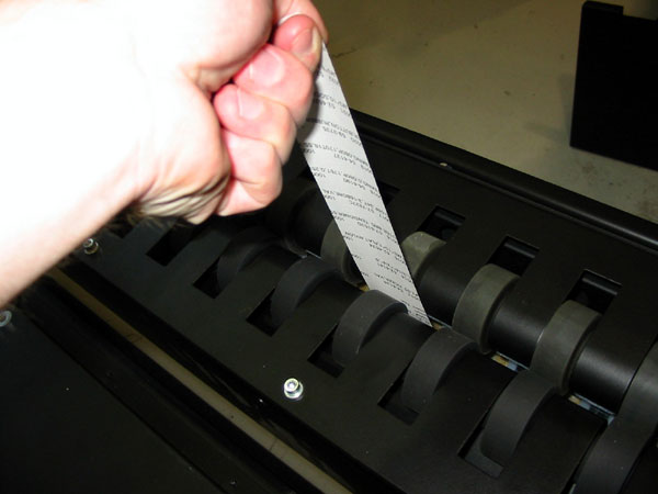
- Feed an approximately 38 mm to 50 mm wide piece of white paper into one pair of wheels until the rollers have applied traction, then hold the paper in place.
- Move the paper to other pairs of wheels along the length of the rollers in order to compare the level of traction in each area.
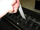
- If the traction is strongest in the center section, decrease the preload in each screw by approximately 1/8 turn. Repeat the traction test.
- If the traction is strongest at the ends of the rollers, increase the preload in each screw by approximately 1/8 turn. Repeat the traction test.
- If the traction is not uniform from one end of the rollers to the other, the SSR unit may be mounted incorrectly in the machine, or the backbone may have been twisted during manufacturing. Verify the position of the mounting rails, then follow the twisted backbone procedure below:
This procedure is used to check for equal traction on each end of the rollers after the preload is set.
CAUTION:
Be careful when doing the traction test, as the rollers are turning and present a pinching hazard.Twisted Backbone Procedure
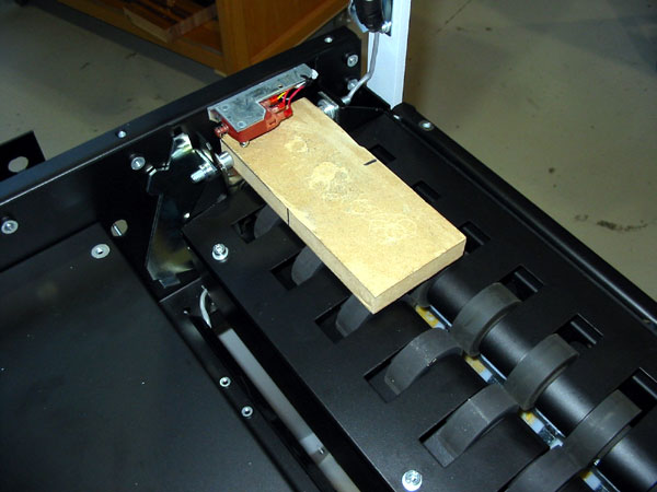
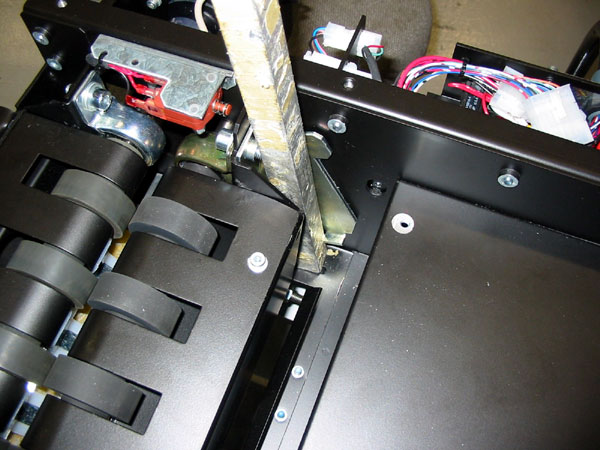
- Place a stopper block, approximately 3/4 in to 3 in, above the roller bearings at the end where the traction is greatest. Once the block is in place, the rollers should not be able to contact each other.
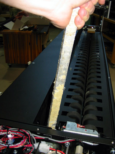
- Place a prybar at the end of the moving backbone where traction is the lowest (i.e., at the opposite end from the stopper block). Apply torque to the backbone until the rollers move closer together.
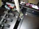
- Repeat the traction test until the traction is uniform. The roller preload procedure may need to be repeated if the traction is lesser or greater in the center section.
This procedure is only required if the traction test demonstrates an unequal traction on each end of the rollers after the preload is set.
Roller Closed Sensor Calibration
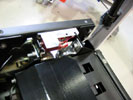
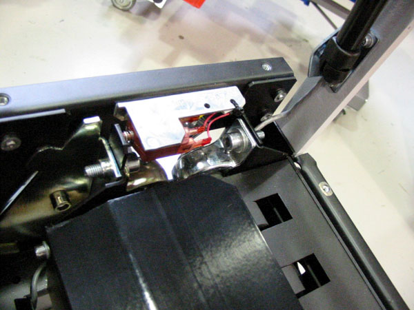
- Install the switch and bracket onto the SSR motor drive unit body, leaving the M4 nylock nuts loose.
- Close the rollers, using the pneumatic system.
- Ensure that the rollers are not being obstructed, and that they have are contacting each other uniformly.
- Move the limit switch bracket until the switches are about 1/2 mm from their bottomed out position. Tighten the M4 nylock nuts. If the switches are allowed to bottom out, damage will occur during prolonged use.
The roller closed sensor is a safety mechanism to prevent the compactor plunger from operating when the rollers are forced apart by an object other than paper.
Compactor End of Stroke Sensor Calibration
- Loosen off the adjustment screws until the brackets are slack. The retract sensor bracket has two screws and the extend bracket has three screws.
- Manually cycle the compactor mechanism (make sure the pneumatics are disconnected) to the end of stroke in each direction to check for interference.
- Connect the pneumatics and set the compactor to the retracted position. Adjust the bracket so that the switch is about 1/2 mm from bottoming out. The retract switch button is visible through a small window in its mounting bracket.
- Set the compactor to the extended position.
- Position the mounting bracket so that the switch is also about 1/2 mm from the bottom out position.
- Tighten the mounting screws. The compactor may need to be disabled and manually cycled out of the way to gain access to the third bracket mounting screw.
- Cycle the compactor using Service Shell. Verify that the sensors are functioning correctly.
The compactor position switches are mounted on the underside of the motor drive unit. Each switch is mounted on a bracket, fastened to the underside of the motor drive unit with slotted holes inthe direction of adjustment.
07 Oct 2003