Dolev 4press - Assemblies
Mainframe - Solenoids
Main Frame
(A)
Main Frame
(B)
Main Frame
(C)
| Affected Models: |
Dolev 4press |
| Affected Assemblies: |
Film Loading Drawer, Film Unloading Drawer |
| Affected Parts: |
Solenoid, Solenoid Mounting Bracket |
| Special Tools Required: |
None |
The Imagesetter uses electric solenoid mechanisms to assist in
opening its two drawers:
- Film Unloading Drawer Solenoid
- Film Loading Drawer Solenoid
These solenoids may require replacement due to malfunction or
excessive wear.
Overview
The lower drawer solenoid is located near the lower drawer latch
mechanism on the right side of the Imagesetter.
The Unloading Drawer solenoid is attached to the Imagesetter main
frame. In most cases, only the solenoid casing needs to be replaced. Generally, there is
no need to remove the solenoid pin and locking toggle.
Unloading
Drawer Solenoid Unit
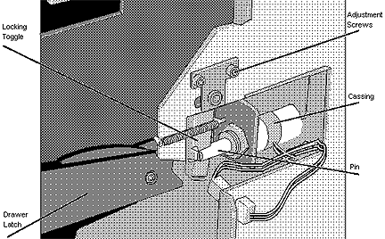
Disassembly
- Open the Film Unloading Drawer.
- Locate the solenoid unit and disconnect its electronic cable.
- Carefully release the solenoid unit’s tension spring.
- Remove the solenoid:
- Using a wrench, loosen and remove the large collar nut located at the
front end of the solenoid. (This is the end where the solenoid pin enters the casing.) The
solenoid casing will be freed.
- Pull the solenoid casing out of the Imagesetter.
Assembly
- Place the new solenoid casing on the mounting bracket and insert the
solenoid pin (still attached to the mounting bracket) into the casing.
- Replace and secure the large collar nut on the solenoid casing.
- Re-attach the solenoid unit’s tension spring.
- Re-attach the solenoid unit’s electronic cable.
Adjustment/Calibration Procedure
 In most situations,
no adjustment is necessary.
Two small hex screws (located on the external side of the solenoid
mounting) are used to adjust the final position of the solenoid locking toggle in relation
to the Unloading Drawer latch.
- Locate and loosen the two (2) hex adjustment screws.
- Adjust the solenoid locking toggle so that the Drawer’s closure
latch fits snugly beneath it when the Drawer is closed.
- Retighten the two (2) hex adjustment screws.
Test Procedure
- Close the Film Unloading Drawer.
- Ensure that the Drawer’s closure latch fits snugly beneath the
locking toggle attached to the solenoid pin.
- Using the Control Panel utilities, open and close the Drawer several
times and check for proper Drawer operation.
Overview
The upper drawer solenoid is located near the upper drawer mechanism
on the left side of the Imagesetter.
The electric solenoid is attached to a mounting bracket. In most
cases, only the solenoid itself needs to be replaced. However, the upper drawer solenoid
cannot be removed without also removing its mounting bracket. The mounting hardware is
reinstalled after the new solenoid unit has been mounted on it.
Removing the Upper Solenoid
Mounting Bracket
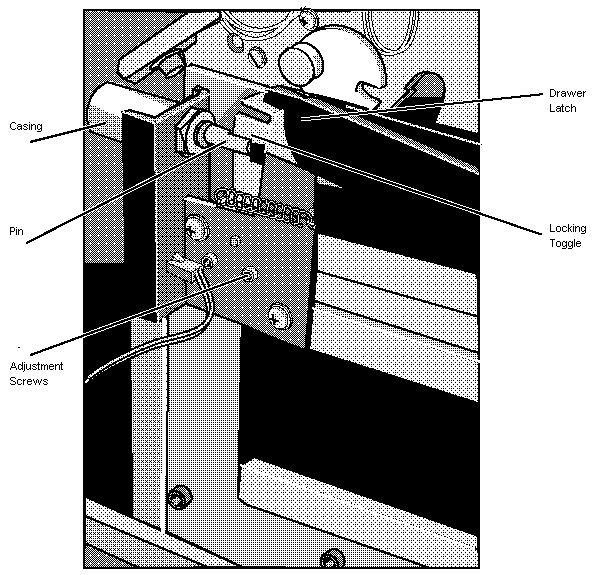 Click
to see the full size
Disassembly
- Open the Film Loading Drawer.
- Locate the solenoid unit and disconnect its electronic cable.
- Carefully release the solenoid unit’s tension spring.
- Remove the solenoid:
- Using a wrench, loosen and remove the large collar nut located at the
front end of the solenoid. (This is the end where the solenoid pin enters the casing.) The
solenoid casing will be freed, however it can not be withdrawn until you remove it
mounting bracket.
- Remove the two (2) Philips screws from the external side of the
solenoid mounting bracket and the one (1) flathead screw from the internal side of the
solenoid mounting bracket. The bracket will now be freed.
- Move the freed mounting bracket clear of the Imagesetter and pull the
solenoid casing out of the Imagesetter.
Assembly
- Place the new solenoid casing on the mounting bracket and insert the
solenoid pin (still attached to the locking toggle) into the casing.
- Reinsert the one (1) flathead screw to the internal side of the
solenoid mounting bracket and the two (2) Philips screws to the external side of the
solenoid mounting bracket.
- Replace and secure the large collar nut on the solenoid casing.
- Re-attach the solenoid unit’s tension spring.
- Re-attach the solenoid unit’s electronic cable.
Adjustment/Calibration Procedure
Two small hex screws (located on the external side of the solenoid
mounting) are used to adjust the final position of the solenoid pin in relation to the
film loading drawer.
- Locate and loosen the two (2) hex adjustment screws.
- Adjust the solenoid pin so that the Drawer’s closure bracket
fits snugly around it when the Drawer is closed.
- Retighten the two (2) hex adjustment screws.
Test Procedure
- Close the Film Loading Drawer.
- Ensure that the Drawer’s closure latch fits snugly over the
locking toggle attached to the solenoid pin.
- Using the Control Panel utilities, open and close the Drawer several
times and check for proper Drawer operation.
|

