Home | Contact Us | Submit Troubleshooting Info | Search | Help
Output | Software Solutions | Proofing | Color, Screening and Calibration | Scanning | Digital Photography | Consumables | POS
Home | Contact Us | Submit Troubleshooting Info | Search | Help
Output | Software Solutions | Proofing | Color, Screening and Calibration | Scanning | Digital Photography | Consumables | POS
Dolev 4press
Site Preparation
- Overview
- Pre-Installation Checklist
- Electrical Requirements
- Space/Floor Requirements
- Film Processor & Safety Light
- Environmental Requirements
- Layout Dimensions
BEFORE INSTALLING THE IMAGESETTER READ THROUGH THIS SECTION VERY CAREFULLY
Overview
This section describes how to prepare the customer site for Dolev 4press Imagesetter installation. It includes details on such requirements as:
- Floor space
- Electrical
- Environmental
- Communications
- On-line processor
Pre-Installation Checklist
Before arrival of the Imagesetter at the installation site, you should prepare a final layout of the site, and determine that all requirements will be met. Work together with the customer to ensure that you have all pertinent details:
Requirement Item Met ? 1. Electrical power 
2. Isolation transformers or power conditioners 3. Circuit breakers and sockets 4. Grounding network 5. Air-conditioning power 6. Space 7. Cable routing provisions 8. Communication network 9. Water supply 10. Illumination 11. Fume exhaust system 12. Delivery route: doors, corridors, elevators 13. Protection from direct sunlight 14. Anti-static flooring 15. Thermometers and humidity meters/recorders 16. Storage space 17. Access to and operation of the system 18. Inline processor 19. Phone lines (two outlets) 20. Preparation of technical drawings 21. Preparation of electrical wiring 22. Preparation of air-conditioning plans 23. Air pressure 24. Fire detection and prevention For additional guidance on site preparation, refer the CreoScitex Preparation Guide, CreoScitex Doc. No. 745-74181.
Electrical Requirements
General Considerations
The total power consumed by your system will be determined by the system configuration selected. Remember to allow sufficient margin for system expansion when calculating the required electrical capacity.
Electrical Supplies
Each separate piece of equipment will be individually powered from source, allowing maximum permutation of layout, and reduced dependency during operation. Provision of sufficient power sockets must therefore be taken into consideration.
All equipment will operate from standard mains supply sockets. The Imagesetter is switch-selectable to comply with a wide range of voltage applications.
Supply voltage variations of up to ±10% on all selectable voltages. Supply frequency variations of ±2 Hz are similarly acceptable.
The main circuit breaker should be a shunt trip breaker, which trips on loss of voltage. A single phase isolated outlet is required for the Imagesetter.
Note the following guidelines:
The input power cable (from the building input feeder/main power entrance to the system branch circuit power panel) should be a dedicated line, 5-wire protected cable, not longer than 30 m (100 ft).
Output circuit breakers should be used for every branch circuit (outlet). Each circuit breaker should be labeled, identifying its load relationship, and correspondence to outlet.
Additional isolated single phase outlets are required for service purposes.
Special codes and regulations may exist covering the installation of electrical facilities in general, and in computer sites in particular. Ensure that site construction complies with these local codes before the system is delivered.
Power Line Disturbances
The reliable operation of computer systems depends on the availability of relatively noise-free AC power.
Lighting, line faults, or the power switching, commonly found in machinery or equipment in office or factory environments, can generate line transients which far exceed the peak value of the applied voltage. If not attenuated, these micro-second pulses can disrupt system operation.
NOTE THE FOLLOWING GUIDELINES
- Limited power supply attenuation has been incorporated into your equipment to minimize the possible effects of disruptive factors (such as transient and instantaneous power interruptions).
- Since these conditions are unique to your particular site, we recommend additional protection, including provision of a mains input circuit breaker with shunt trip, and an isolation transformer with common mode noise attenuation of greater than 120 dB.
- It is recommended that the power conditioner isolation transformer used should be one which includes a power distribution system (output circuit breakers and receptacles). When installed in the system room, the conditioner/transformer will make system installation easier and reduce installation time and cost.
- All other potential noise-generating equipment (e.g., fans, fluorescent lighting and air-conditioning system) must be separated from the power source used for the system.
Grounding
The power ground system for 50 Hz sites should include the 220 VAC and 380 VAC grounds, tied back to the main power ground point of the building by means of a 40 mm solid copper wire (7 mm in diameter).
At 60 Hz sites, 220 VAC, 110 VAC, and 208 VAC grounds tied by AWG #1 solid copper wire are required.
Grounding requirements for the Imagesetter—and all equipment communicating with it—should be observed to ensure trouble-free operation.
Grounding requires the following:
- Grounding wires must be insulated and at least equal in size to the phase conductors.
- Ground impedance less than 2 ohms.
- A single point and dedicated ground.
- The power stabilizer equipment should be supplied by three (3) uninterrupted phase wires, and one uninterrupted copper ground wire, from the main building entry service panel. They should run in the same conduit and be at least equal in size to the phase wires.
- Verify that neutral and ground are bonded together in the main building entry service panel, and that there is a good earth ground at this point of not more than 2 Ohms impedance.
- Each system load (Imagesetter, Host, etc.) will be fed through an isolated ground outlet and have a separate ground, as well as neutral and phase line of equal size wire. Chained neutrals or grounds are not permissible.
- All ground wires from isolated ground outlets will be kept isolated from building ground and terminated only at the ground bus of the power stabilizer.
- Other equipment, not on the power stabilizer but communicating with the Imagesetter must have a reference ground wire installed between the power stabilizer ground bus and that piece of equipment.
These instructions do not replace any enforced government or local standards. The installer should check the applicable electrical code and assure full compliance.
Cables
If cables must be routed through a wall, the holes in the wall should be as follows:
- Round holes should be 10 cm (4 in) in diameter
- Square holes should be 8.9 cm (3.5 in) in diameter
No electrical wiring (stabilized or unstabilized) may run in the data cable conduit.
Space/Floor Requirements
Floor Space
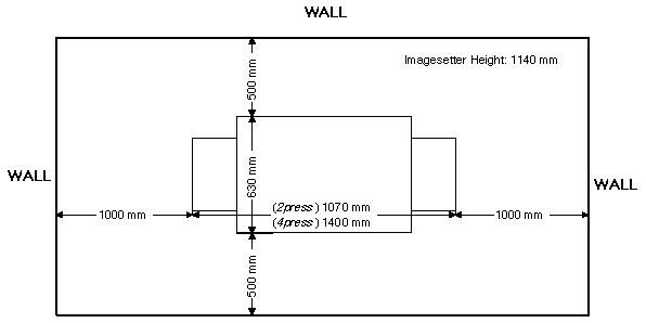
Depending on the model, the Imagesetter requires between 5.7 and 6.32 cubic meters of space. This measurement reflects the area required around the Imagesetter, to allow for unimpeded work and considerations such as heat dissipation. The following figure depicts the minimum floor dimensions required for proper operation of the Imagesetter. [RDR2]
Imagesetter Space RequirementsNOTE: This diagram does not depict use of an on-line processor. Refer to On-Line Processor Requirements, for details.
Imagesetter Weight
The Imagesetter weighs between 180 and 230 kilograms and rests on four symmetrically-placed cushioned legs. Most standard industrial floors are strong enough to support the Imagesetter, though actual room dimensions and additional equipment at the site should be considered.
Film Processor & Safety Light
Safety Light Bright Cyan
The standard film will be orthochromatic (red sensitive), requiring a bright cyan safety light. (For more details, refer to the film manufacturer’s recommendations.)
Although the film must be loaded into its cassette in a suitable darkroom, following this initial step, routine film handling can be under normal daylight conditions. Direct sunlight should always be avoided.
Recommended Inline Processor Manufacturers
The following manufacturers have designed ILP models which are compatible with the Imagesetter:
- Glunz & Jensen
- Lüth
- Echo Graphic
Film Types
Environmental Requirements
Cleanliness
Cleanliness of standard laser operating environment, i.e., up to 0.168 milligram/M (Class 4, B.S. 5295) as follows:
- Up to 200,000 particles/M³ when greater than 5 microns
- Up to 40,000 particles/M³ when greater than 10 microns
- Up to 4,000 particles/M³ when greater than 25 microns
Filters in the air conditioning system will be able to block 60% of all 10 micron dust particles.
Static Electricity
Use of floor carpeting is not recommended in the Imagesetter area. If carpets will be used, only anti-static carpets will be installed at the site. Their size should be at least 2.5 m (8 ft) in all directions of Operator's access.
Air Conditioning
Sufficient air-conditioning should be present to provide heat dissipation for the Imagesetter (1500 BTU per hour) plus all additional equipment residing in the System room plus a minimum 25% safety margin.
Example: (all in BTU/hour)
Imagesetter: 1500 Host: 2500 Light Table: + 3500 Other Misc: 1500
Safety Margin:
(25% of above)+ 2250
Total Heat: 11250
- The Imagesetter requires a constant air temperature of 24°C ± 2°C and relative air humidity of 55% ± 5%.
- The maximum temperature variation is 5°C per hour.
- The minimum allowed temperature is 10°C.
Note the following guidelines:
- It is recommended that the air flow in the System room be maintained above normal air pressure, in order to prevent dust from entering the room.
- The System room should ideally contain both a thermometer and hygrometer, permanently mounted in a central location.
Film Handling
The standard film will be orthochromatic (red sensitive), requiring a bright cyan safety light. (For more details, refer to the film manufacturer's recommendations.)
Although the film must be loaded into its cassette in a suitable darkroom, following this initial step, routine film handling can be performed under normal daylight conditions. Direct sunlight should always be avoided.
Layout Dimensions
Depending on the model, the Imagesetter requires between 5.7 and 6.32 cubic meters of space. This measurement reflects the area required around the Imagesetter, to allow for unimpeded work and considerations such as heat dissipation. The following picture depicts the minimum floor dimensions required for proper operation of the Imagesetter.
Imagesetter Space RequirementsNote: This diagram does not depict use of an inline processor. Refer to the Inline Processor Requirements for details.