Procedure
|
|
Removing the cutter system
- Shutdown the machine, and then disconnect the main power cable.
- Open the right and left doors of the machine.
- Open the rear cover of the machine.
Note: If the configuration includes an online processor, push
the plotter away from the online processor.
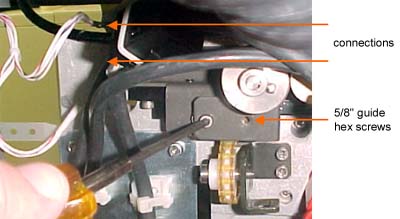
- On the left side of the machine, disconnect the encoder connector and the 3-pin
connector (knife HP detector), and then remove the two hex screws from
the 5/8" guides.
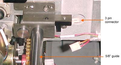
- From the right side of the machine, disconnect the 3-pin connector
(knife EP detector) and then pull the 5/8" guides out of the
machine.
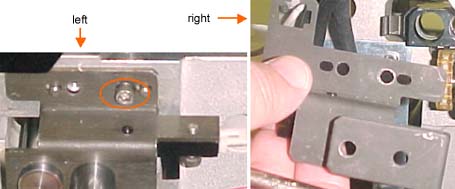
- On each side of the machine, remove the two 8-32*1/2" screws
and spring washers from the cutter holder block, and then remove the
cutter holder block from the machine.
- To enable ease of access, slide the knife to the center of the drum
by pulling the chain.
Installing the cutter assembly (507C38840A)
Important: Do not tighten any of the screws,
unless the instructions specify. At the end of the procedure, you will be
instructed to tighten all screws, but do not over-tighten.
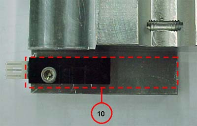
- Install a photo interrupter (10) in the left and right cutter
holder blocks (6 and 7). The pins should point toward
the back of the machine.
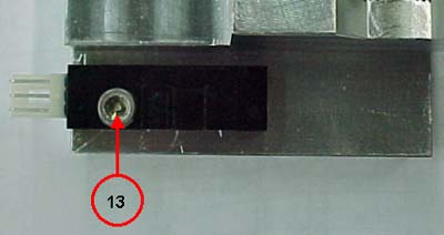
- Secure each photo interrupter in the cutter holder block with one
8-32*1/2" (13) screw and spring washer (16), and then tighten the
screws.
Note: Do not over-tighten—over-tightening can cause the
plastic to break.
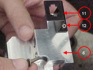
- Install the mini-fit 4-pin holder (11) in the left cutter
holder block (6) with two
6*32-1/4" screws (12), and tighten the screws.
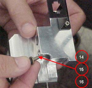
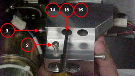
- Install the left cutter holder block with 8/32*5/8" screws
(14),
flat washers (15) and spring washers (16). To
adjust the position of the left cutter holder block, move it to the
right and left.
Note: Use only the screws from the kit (380A05081).
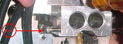
- Install the right cutter holder block with 8/32*5/8" screws
(14),
flat washers (15) and spring washers (16). To adjust the position of
the right cutter holder block, move it to the right and left, and
up and down.
Note: To prevent diagonal cutting, loosen
the two screws on the right side of the right cutter holder block and move
the right cutter holder block up and down. Test and readjust if
required.
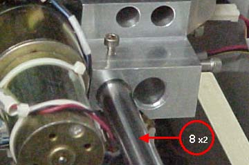
- Install the 5/8" guides for polyester (8).
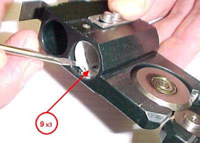
- Carefully remove the nylon bearings from the cutter system, and
then install two new nylon bearings (9) in the hole close to the
cutter, and one in the other hole.
When removing the nylon bearings from the cutter
system, be very careful not to scratch the knife.
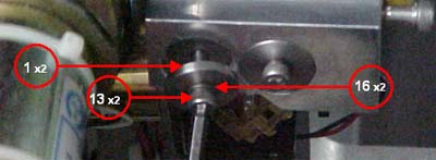
- Insert the 8/32*1/2" screws (13) spring washers (16) and
stretching washers (1) on both sides of each guide.
- On the right side, tighten the 8/32*1/2" screws (13) screws.
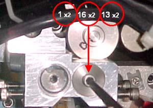
- On the right side, tighten the two 10-31 con screws (5).
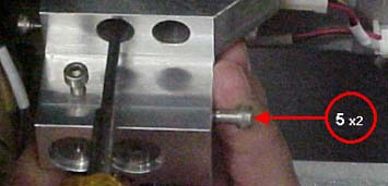
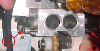
- On the left side
"stretch" the guides with the
8-32*1/2" screws, and then lock the guides by tightening the four
10-24 con
screws (4) on the side of the left cutter holder block.
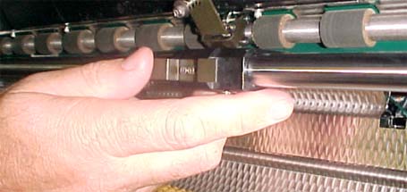
- Verify that the cutter system moves smoothly along the 5/8"
guides.
- Secure the 5/8" guides by tightening the
8/32*1/2" screws (13) on the left and
right cutter holder blocks.
-
Repeat step 12.
- Verify that all screws on the left and right cutter holder brackets
are properly tightened.
- Connect the 3-pin
connector (knife HP detector) on both sides of the machine, and then
connect the encoder connector on the left side of the machine.
- Close all doors and covers.
- Connect the main power cable, and then start the machine.
Test
- Reload polyester media.
- Advance several polyester sheets.
- Verify that the cut is straight.
|

