Dolev 4press -
Installation
Setup
The installation procedure requires access to Imagesetter internal
assemblies, and so is performed with Imagesetter doors open.
 The procedure
for opening the Imagesetter doors is identical for both left and right
doors.
- Release the three (3) securing bolts in the following sequence:
bottom, middle and top. There is no need to remove these bolts, as the Imagesetter door
will spring open when they are loosened.
- Open the door.
- Repeat for both left and right Imagesetter doors.
The Imagesetter is at the proper height when all of its wheels are
raised just above the floor. A standard leveling instrument should be used to ensure that
the Imagesetter is level.
In this instance, level means that the Imagesetter is situated on a
uniform horizontal plane at all four corners.
1. Adjust the level adjustment mounts on each of the four (4)
Imagesetter legs to fix the machine at a level position.
Refer to (2) lock nuts to fix the machine
Detail - Leveling Mounts
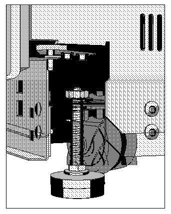
Each mount uses two in a level position. [RDR5]
- Loosen the top 3/8-inch lock nut. You may find it easiest to hold the
bottom lock nut in position with a second wrench.
Turn the bottom hex nut clockwise (to raise) or counterclockwise (to lower) the mount to
the required height.
- To reach the proper height for each mount, raise the mount until the
nearby wheel begins to rotate freely above the floor, Use slight pressure fingertip
pressure to rotate the wheel.
- When adjustment is complete, tighten the top hex nut to lock the
current position.
Hint: It is best to adjust the height of each of the four mounts before
you lock any of the mounts in place. Lock the hex nuts only when all four legs are set to
their proper height.
- Attach the four (4) lower skirts framing the Imagesetter. (These
skirts are shipped disassembled from the Imagesetter.)
From each side of the Imagesetter, align the matching skirt with its attachment holes and
push firmly.
There are
two skirt types—one type for Imagesetter front and rear and
a second type for Imagesetter left and right. Ensure that the attachment
tabs and springs for each skirt match the correct attachment holes
on the Imagesetter.
Overview
The Imagesetter is shipped with numerous safeguards that prevent
excessive movement of internal parts during transport.
- Optomechanical to Chassis Shipping Brackets
- Optics Carriage Transport Locking Plates
- Film Guide Upper and Lower Door Screws
These safeguards need to be removed prior to Imagesetter operation.
The locations of these safeguards are depicted in the following figure. Detailed
procedures for their removal follow.
Optomechanical to Chassis Shipping Brackets
These special mounting brackets lock the Optomechanical Assembly
into place during transport. There are three (3) brackets, one on each side of the
Imagesetter, and one at the center rear.
Two Side Brackets
- Loosen the three (3) 9/64-inch hex screws securing each mounting
bracket, as depicted in Left and Right Optomechanical to Chassis Shipping screws.
Attention: Do not remove these
screws!
- Repeat for both left and right sides of the Imagesetter.
Rear Bracket
- Loosen the two (2) 9/64-inch hex screws securing the mounting
bracket, as depicted in Rear Optomechanical to Chassis Shipping Screws
- Raise the mounting bracket slightly, about 3 mm. This provides
sufficient clearance for the Optomechanical Assembly during routine operation.
- Retighten the two (2) 9/64-inch hex screws securing the rear bracket.
Optics Carriage Transport Locking Plates
These plates secure the Dynamic Optics Carriage in place during
transport. They are colored red for easy identification.
- Remove the two (2) 3/32-inch hex screws and the red plates from the
left and right sides of the carriage.
- Store this hardware with the accessories kit for possible later use.
Film Guide Door Screws
These screws prevent the Film Guide Upper and Lower Doors from
excessive movement during transport.
Upper Door
Remove the two (2) 9/64-inch hex screws securing the Film Guide
Upper Door, located at both left and right sides of the Imagesetter, as depicted in Film
Guide Upper Door Screws. Store these screws with the Accessories Kit for possible later
use.
Lower Door
Remove the two (2) 9/64-inch hex screws securing the Film Guide
Lower Door, located at both left and right sides of the Imagesetter, as depicted in Film
Guide Lower Position. Store these screws with the Accessories Kit for possible later use.
The Film Path Selector determines whether exposed film is output to
the accumulating cassette drawer or to the on-line processor. This switch is located on
the left side of the Imagesetter, as depicted in Film Path Selector
To direct exposed film to the accumulating cassette, move the switch
counter-clockwise.
To direct exposed film to the on-line processor, move the switch
clockwise.
Overview
Prior to connecting the electrical power supply, ensure that all
voltage settings, fuses and cords are in full accordance with local standards.
Voltage Settings and Fuses
At the factory, the Imagesetter is set to a line voltage of 220
volts. If this setting does not match your local current, you will need to change both the
position of the voltage selector and the Imagesetter fuses.
The current voltage selector setting appears in a small window on
the Electronic Power Drawer Assembly located on the rear side of the Imagesetter.
 The Imagesetter
is a precise instrument and its components are sensitive to small
fluctations in electrical current. Before proceding, it is recommended
that you measure the electrical voltage coming from the wall in order
to determine its exact range.
Use the following table to determine the required setting:
| Measured Voltage |
Voltage Selector Setting |
Required Fuses |
| 90 V to 110 V |
100 V |
2 x 8A |
| 111 V to 135 V |
120 V |
2 x 8A |
| 180 V to 230 V |
220 V (Factory Setting) |
2 x 4A |
| 231 V to 265 V |
240 V |
2 x 4A |
To change the voltage setting:
- Ensure that the power cord is not connected to the Imagesetter.
- Locate the Electronic Power Drawer Assembly at the rear left side of
the Imagesetter.
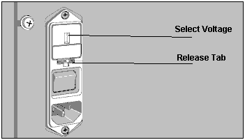
- Remove the fuse holder from the Unit to provide access to the voltage
selector. Place a small pen knife or flat head screwdriver under the tab at the bottom of
the the fuse holder, and lift the tab slightly to release the holder. See figure below.
Opening the Fuse Holder
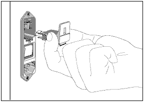
- Once it is released, pull the holder completely out of the Unit, as
depicted in the following figure.
Removing the Fuse Holder
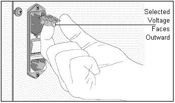
- Remove the voltage selector from the Unit. Grasp the selector and
pull it straight out. Note that voltage settings are printed on each of its four posts, as
depicted in the following figure. The current voltage setting for the Imagesetter should
face outward for viewing through the fuse holder window.
Selecting the Voltage Setting
- Rotate the voltage selector until the required voltage setting faces
outward for viewing through the fuse holder window. (Refer to the table above for the
correct setting.)
- Replace the voltage selector in the Electronic Power Drawer Assembly.
Push the selector slightly to ensure that it is completely inserted.
- If required, change the fuses in the fuse holder to a type which
matches the local current. (Refer to the table above for the correct setting.)
- Replace the fuse holder in the Unit. When properly seated, the holder
will snap into place with only slight finger pressure.
Power Cord
Once the correct voltage setting has been selected, connect the
appropriate power cord to the power inlet plug of the Electronic Power Drawer Assembly.
Plug the opposite end of the cord into the electrical power supply located in the wall. Do
not turn on the power switch yet!
Overview
The Imagesetter receives all control and exposure data via fiber
optics cable from the Host.
Optional control
data from a second PS/2* Host can be received also via Host A or Host
B ports at the Imagesetter rear.
Before making data connections to the Host, settings on the various
Imagesetter electronics boards must be checked.
Other Boards
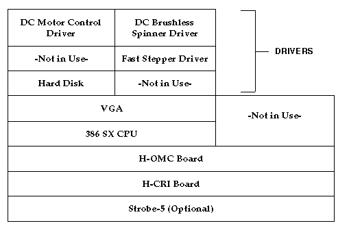
The Electronics Unit (also called the E-Box) houses most of the
Imagesetter's electronics boards. The following figure depicts each board and it location.
Boards in the Electronics Unit
BOARD CONNECTIONS
The Imagesetter is shipped with all Electronics Unit boards
connected to their ports. If necessary, refer to identification information located on the
Imagesetter to verify that all connections are correct.
CHECKING BOARDS
In the event of an operational failure during Imagesetter
installation, you should ensure that all required boards are in their correct positions in
the Unit.
- Open the Electronics Unit cover by removing its two (2) spring-loaded
retaining screws. Remove the cover completely from the Unit.
- Examine each slot in the Unit and identify the boards in each. Refer
to the figure above to verify board types and positions. You may need to release the
boards and pull them out slightly in order to identify them.
Imagesetter Power On
Once you have ensured that all Imagesetter boards and connections
are in position and are correct, it is safe to power-on the Imagesetter.
- Ensure that the Imagesetter is safely connected to the electrical
supply.
- Turn on the power breaker switch on the Electronic Power Drawer
Assembly on rear side of the Imagesetter.
- Turn on the power switch located on the upper rim of the Imagesetter
control panel.
Host Power On
Turn on the power of the PS/2* Host system. (Refer to the PS/2*
manuals, if necessary.)
Software Version Check
Before proceeding, ensure that the operating software being used on
both the Imagesetter and the Host are compatible.
- Following power-on, the Imagesetter automatically loads its software.
If at anytime
you should need to load the system manually, enter ht at the display
prompt: HADAS>ht
The system will load, and the Imagesetter control screen will be displayed.
- When the system has loaded, note the current Imagesetter software
version identifier appearing at the top center of the Imagesetter display.
- Determine the software version currently running on the PS/2* Host.
(Refer to the PS/2* manuals, if necessary.)
- Ensure that the Imagesetter software version is fully compatible with
the software currently running on the PS/2* Host.
Updating Imagesetter Software
If the current software versions are not compatible, you will most
likely need to update the operating software on the Imagesetter.
- Obtain Imagesetter software which is compatible with the PS/2* Host
operating software.
Attention: If different update instructions accompany the update disk, then follow the
new instructions.
- Ensure that the software update disk is write-protected. Then insert
the new software disk into the floppy drive at the Imagesetter rear.
- Exit the System by pressing <Control-E> on the control monitor
keyboard.
- Make the following entries at the System prompt:
HADAS>a:
HADAS>update
The operating system software update will be executed.
As part of
the software update, the old operating system is backed up to a
directory called oldver.
- Reset the Imagesetter before continuing operation.
Check VLSI DIP Switches
The VLSI board is located at the bottom of the Imagesetter and is
accessed from the left Imagesetter door. The board connects to the Host for exchange of
both control and exposure data.
VLSI Board Connections
The VLSI board connects to the Host via both fiber optic link.
To connect the VLSI to the Host:
- Remove the Imagesetter rear panel by loosening its 4 Philips-type
screws.
- Route one end of the multi-mode fiber link cable from the outside
rear of the Imagesetter, through the rear panel area and over the fan assembly located at
the right side of the machine.
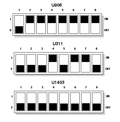
VLSI Board DIP Switch Locations
- Connect this end of the fiber link cable to the fiber optic
connectors on the Imagesetter VLSI board. The two (2) connectors use a "bayonet"
mount.
If you are also installing a PS/2* system:
If you have not yet installed the fiber optics cable on the PS/2*,
there is no distinction between TX and RX connections on the fiber optics cable. Simply
connect one end of each cable to the TX1 and RX1 plugs on the VLSI board. Once the PS/2*
system is powered on, you can check for proper TX/RX connection.
If your PS/2* system is already operating:
Insert the receiving (RX) cable connector into the plug marked TX1
on the VLSI board. Insert the transmitting (TX) cable connector into the plug marked RX1
on the VLSI board.
Hint:
With the PS/2* Host powered on, the TX connector on its SFLM board will emit a fine red
light. Attach one fiber optic cable end to this connector. This is the transmitting (TX)
cable. When connected, a fine red light will be emitted from the opposite tip of this
cable. Connect this cable to the receiving plug RX1 of the VLSI board on the Imagesetter.
Now simply connect the second fiber optics cable to the remaining plugs.
- Connect the free end of the fiber link cable to the SFLP board in the
PS/2* Host computer. The TX cable should connect to the RX plug of the SFLP on the PS/2*.
VLSI Board Switch Settings
The VLSI board must be configured correctly for the current system.
There are DIP switches on the board for this purpose. In the event of a communication
failure with the Host, check these switch settings carefully.
To check the VLSI board settings:
- Open the left Imagesetter door.
- Disconnect the fiber optics cables and the Data Cable from the VLSI
board.
- Remove the VLSI board access cover at the bottom of the Imagesetter
by loosening the two (2) spring-loaded retaining screws on the cover's left side.
- As shown in the following figure, pull firmly on both red release
clips located at either end of the board, and slowly withdraw the board from the
Imagesetter.
Hint:
For easiest access to the VLSI board, you can withdraw the entire D-Box by loosening the
two (2) spring-loaded retaining screws on either side the box. Pull the D-Box out slightly
as depicted in the following figure.
- Examine the VLSI board's DIP switches to ensure that they are
set correctly for your configuration. Refer VLSI
Switch Settings (1) for their locations on the board.
If necessary, set the DIP switches according to the current system configuration. Refer to
the appropriate configuration in the folllowing figure.
VLSI Switch Settings (2)

- Reinsert the VLSI board. Reconnect the fiber optics cables to their
proper ports. Reconnect the Data Cable to the J3 port.
Powering On/Off the Machine
to be defined
SOFTWARE VERSION CHECK
Before proceeding, ensure that the operating software being used on
both the Imagesetter and the Host are compatible.
- Following power-on, the Imagesetter automatically loads its software.
- When the system has loaded, note the current Imagesetter software
version identifier appearing at the top center of the Imagesetter display.
- Determine the software version currently running on the PS/2* Host.
(Refer to the PS/2* manuals, if necessary.)
- Ensure that the Imagesetter software version is fully compatible with
the software currently running on the PS/2* Host.
Updating Imagesetter Software
If the current software versions are not compatible, you will most
likely need to update the operating software on the Imagesetter.
- Obtain Imagesetter software which is compatible with the PS/2* Host
operating software.
Attention: If different update
instructions accompany the update disk, then follow the new instructions.
- Ensure that the software update diskette is write-protected. Then
insert the new software diskette into the floppy drive at the Imagesetter rear.
- Reset the Imagesetter. The Imagesetter will boot from the diskette
and the operating system software update will be executed.
- Remove the update diskette from the Imagesetter floppy drive.
- Reset the Imagesetter again.
|

