Dolev 4press; Dolev 4news
Linearity Registration Correction Using the Strobe Tables
Author/Submitter: A.
Posner (08/07/97)
Document Released: 08/07/97
Product Family: Imagesetters / Platesetters
The Strobe board in the Dolev 4press
can be used for Linearity correction by using the Grid setting utility.
Note: It is recommended to use the
"Remote Mode" for this procedure. It will be faster to insert the measurements
into the table.
The correction procedure:
Create a Grid file with the size: H=700mm
and W=550mm.
Each rectangle in the Grid Should be with the size: H=115mm and W=67.5mm.
Create second grid to use as a ruler. Each square should be 67.5 x 67.5 mm.
On both grids it is recommended to use resolution 100 and the lines will be from one pixel
( 10 microns width ).
If you use a Brisque the grids can be exposed after copying them from a CD that contains
the two grids.
Expose the two Grids and make sure that the
overall size ( 700x550) is correct.
If the overall size need correction use the
LD and/or the LS functions.
Using the LD & LS:
Enter the Service Utilities
Setup -> Service -> Dimension setting
Make sure that in the table you will have:
Grid step Height = 115
Grid step Width = 67.5
LD = 1.00
LS = 1.00
Number of Rows = 7
Noise = Yes
If the overall size is not correct adjust
the LS and/or LD as needed.
Theory: LD is the overall factor in the
drum width direction and LS is the overall factor in the Leadscrew direction.
If the overall size of the grid is 541 mm
and not 540 please insert LD=541/540 = 1.002
If the overall size of the grid is 739 mm and not 740 please insert LS=739/740 = 0.9986
Expose two new Grids ( After the LS & LD
correction ).
Enter the Strobe table in the service
utility. ( Setup -> Service -> Grid Setting )
The table will start with the 0 ( Zero ) line in the height and the numbers will be as the
grid width line: 0, 67.5, 135, 202.5, 270, 337.5, 405, 472.5, 540.
The same will continue on the 115 line, 230 line and so on.
We will measure the 67.5 x 115 mm grid and use the 67.5 x 67.5 mm as a ruler. The ruler is
in the height direction ( Leadscrew direction ).
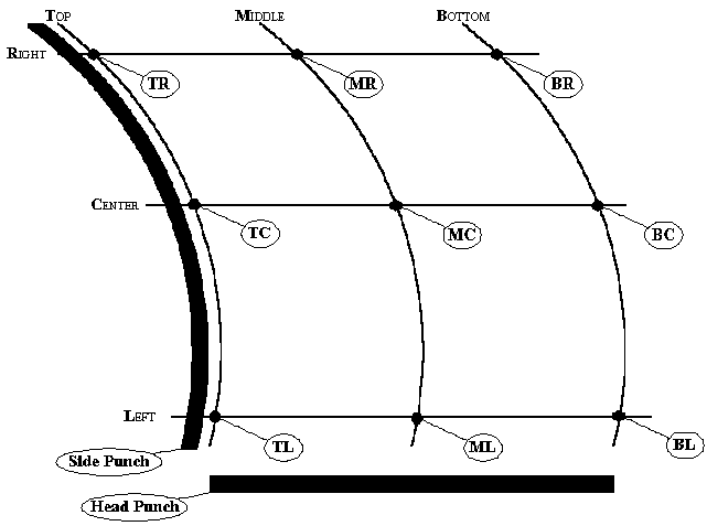
Please note that the 0,0 place on the Strobe
table is the front left corner of the film.
It is the TL corner on the drawing. ( Home position and loading side of the film )
Use one grid as a reference and measure the
other one. You have to rotate the reference grid! ( Remember to use the leadscrew
direction as the ruler ).
Please tape the first grid to the light table ( grfield.lw ) and use the squared one as
the ruler ( grflrf.lw ).
The numbers in the table refers to the left line of the column.
0,0
115,
230,
345,
460,
.......
0,67.5
0,135
0,270
0,337.5
0,405
345,405
0,472.5
0,540
Measure the Grid. Please measure the
left line first and put the numbers in the strobe table. All the numbers in the strobe
table are from the 0 line so if for example the fourth line of the grid ( default value of
202.5 ) is shorter than the ruler line by 50 microns enter in the strobe table the value
202.45. Expose and make sure that you did the right correction on the left line.
Continue only if you are sure that you understood the process. If not read the
instructions again.
Example for a corrected line can be:
0, 67.52, 135.04, 202.56, 270.06, 337.54, 405.02, 472.5, 540.
Continue with the second line ( the
115 line ) and then correct one by one and check each time that the corrections are in the
right direction.
In the Grid Table change only the Width (
The Height, Bow, Can not be corrected )
Expose the Grids again and verify the
correction.
Note: Do not try to correct linearity less
then 50 microns!