Home | Contact Us | Submit Troubleshooting Info | Search | Help
Output | Software Solutions | Proofing | Color, Screening and Calibration | Scanning | Digital Photography | Consumables | POS
Home | Contact Us | Submit Troubleshooting Info | Search | Help
Output | Software Solutions | Proofing | Color, Screening and Calibration | Scanning | Digital Photography | Consumables | POS
Dolev 4press -
Troubleshooting & Diagnostics
|
| Load Exposure Parameters | Exposure format data for the current file is sent from the Host and loaded into memory. Spinner revolution is set to its exposure speed. |
| HP Calibration | The carriage is set to the Home Position (HP), the zero reference point prior to plotting. |
| Light Calibration | The laser is set to the appropriate intensity, as specified in the exposure format parameters sent from the Host. |
| Start Exposure | The Stepper begins operation. Rasterized file data is sent from the Host to the VLSI, where it is processed. The resulting processed data is sent via the HOMC to the LDR, which controls laser light operation. The subsequent laser beam pulses are transmitted via fiber optics cable to the Pentaprism and onto the film. |
| End of Plot (EOP) | An End of Plot signal is sent from the Host and is verified by the Imagesetter. Spinner rotation is lowered to its idle speed. |
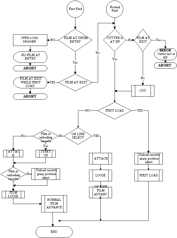
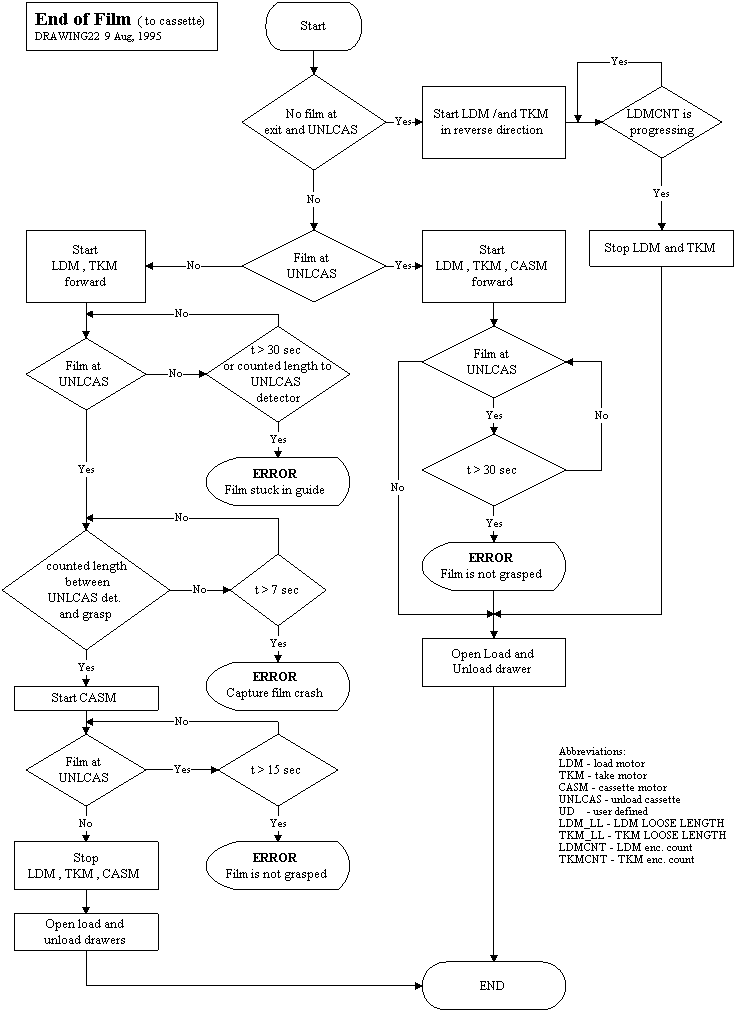
| Advance | Moves the film along film path toward the accumulating cassette or the inline processor.Though actually part of the Film Loading and Unloading process, the Advance step is also integral to the exposure process described here. |
| Carriage to HP | The Dynamic Optics Carriage is returned to the Home Position. |
Following the handshake, rasterized file data begins to stream from the Host to the VLSI board, where processing is performed. VLSI processed data is sent via the HOMC to the Laser Driver, which translates the information into on/off instructions for the laser. Light emitted from the laser is then transmitted via fiber optics cable directly to the Pentaprism, which is spinning inside the Dynamic Optics Carriage.
The Stepper—which has been inactive—begins to operate. The Stepper Driver monitors the Spinner revolution index sent by the Spinner encoder and moves the Dynamic Optics Carriage along the length of the Lead Screw according to this count. Monitoring and motion continue throughout the exposure.
The combined spinning of the Pentaprism and stepping movement of the Dynamic Optics Carriage inside the Imagesetter drum produce the precise coordinates necessary for laser light exposure on the film.
Rasterized data continues to stream from the Host to the Imagesetter until the end of the rasterized data file is reached.