Home | Contact Us | Submit Troubleshooting Info | Search | Help
Output | Software Solutions | Proofing | Color, Screening and Calibration | Scanning | Digital Photography | Consumables | POS
Home | Contact Us | Submit Troubleshooting Info | Search | Help
Output | Software Solutions | Proofing | Color, Screening and Calibration | Scanning | Digital Photography | Consumables | POS
Dolev 800 - Brisque Application Issues
Class Screening
Align to Punch
Overview
Defining Alignment
Alignment Example
Setting Alignment
Rotate 180
Defining a Punch Format
Checking Punch to Center Alignment
The new Align to Punch feature enables you to align an exposed image (a flat or file) to the holes punched on film. This enables you to customize your exposure alignment for different cassette or plate requirements.
This feature is available on Dolev 800 imagesetters.
To provide maximum control of the placement of images on film, you can align an image to any point on the imageable area on film. This may be required for various purposes, such as:
To center an exposed image between the punch holes on film intended for plate preparation on Step and Repeat machines.
To achieve precise image to punch alignment when using tiled flats for plate making.
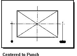
For example: The image below is centered to the punched holes on film intended for a Step and Repeat machine.
Centered to Punch
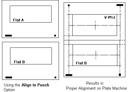
Another example: The two tiles shown below combine to make one plate. It is therefore crucial that they are both precisely aligned to the punched holes and placed a specific distance from the top (opposite the punched holes) of the film.
Tiling
The new Align to Punch option appears both in the exposure dialog and in a Plotter Format.
On Dolev 800 imagesetters this option replaces the Punch (Y/N) parameter.
Note: On the Dolev 800, holes are only punched in the film when one of the Align to Punch options (1 through 12) is selected. When Align to Punch is set to No, holes are not punched in the film.
The Align to Punch feature enables you to align an exposed image (a flat or file) to any position on the imageable area of film, not just to the punch holes. You must first define the coordinates of various positions on film, (such as: (Top, Left), (Middle, Center), (Bottom, Right) and so on) to which you may want to align an image. You can then select one of them in the exposure dialog. The same relative position on the image is then aligned with the selected position on the film.
For example: The left diagram below shows the Top, Left corner of a flat aligned with the Top, Left alignment position on film. The right diagram below shows the center of a flat aligned with the center alignment position on film.
Image to Punch Alignment
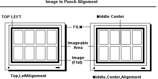
Note: Each position on film is defined by a specific coordinate value, such as: (Top: 10, Left: 10), (Middle: 106, Center: 558.5). The position on the imageable area is automatically calculated according to the dimensions of the whole exposed image, such as: Flat, 1 Up, Step & Repeat.
To enable easy customization of your exposure alignment for different cassette or plate requirements, you can define up to 12 sets of nine coordinates (corresponding to the nine alignment positions) on the imageable area on film. In the exposure dialog, you can then select one of these sets and one pair of coordinates from this selected set to which to align the image.
Each set of nine coordinates is called a Punch Format. These nine positions are defined by specifying six values (which make up nine pairs of coordinates). Each Punch Format contains the following information:
Punch Format
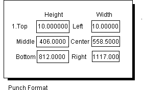
In the exposure dialog, you can select one of the Punch Formats and toggle to the required position in that Punch Format. Each position is defined by a pair of letters, as shown below:
Alignment Points on Film
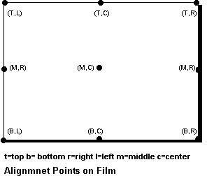
Once you have selected a Punch Format in the exposure
dialog you can toggle to one of the following values: TL, TC, TR, ML, MC, MR, BL, BC or
BR.
TL = Represents the Top, Left corner of the film.
MR = Represents the Middle, Right side of the film.
BR = Represents the Bottom, Right of the film.
MC = Represents the Middle, Center of the film.
and so on.
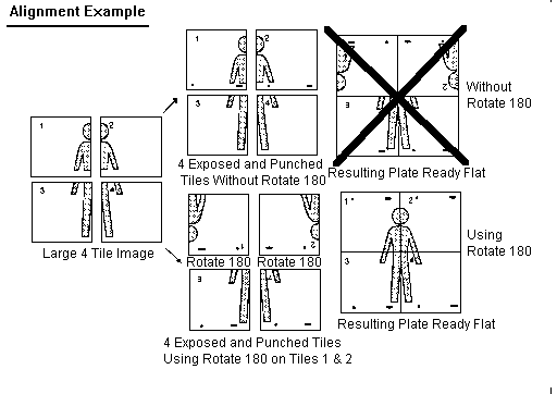
The picture on the left in the diagram shows 4 flat tiles before alignment and exposure.
The center pictures show how each of these flats are aligned and exposed on punched tiles in preparation for placement on a plate (shown in the pictures right).
Flats 2 and 4 are aligned to the Top, Right alignment position on film, and flats 1 and 3 are aligned to the Top, Left alignment position of film. This results in all the tiles being aligned to the center when placed on the plate, as shown below:
Perform the following when specifying the alignment of an image in the exposure dialog, in a Plotter Format, or through PS Defaults.
Note: Before using this option for the first time, follow the instructions in the Checking Punch to Center Alignment section found on the following pages.
Create a Punch Format which defines nine coordinates (representing each of the nine positions) on the imageable area on film. Enter the coordinates of these positions. Refer to the Defining a Punch Format section on the following pages.
In the exposure dialog or in a Plotter Format, toggle the Align to Punch parameter to the number of the Punch Format that you require. This parameter can be toggled to No or to a number in the range of 1 to 12. Each number represents a Punch Format. If you do not remember the number of the required Punch Format, press the Punch Formats <F5> button to view all Punch Formats.
Three new parameters appear in the exposure dialog: Ref. Point, Offset (h,w) and Rotate 180. The Expose Offset parameter is erased, as shown below:
Align to Punch Expose Dialogue
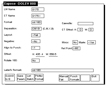
Toggle Ref. Point to the position to which the exposed image is aligned. Toggle to one of the following: TL, TC, TR, ML, MC, MR, BL, BC or BR.
The coordinates of this position are automatically displayed in the Offset parameter. The value is taken from the selected Punch Format. This parameter can not be modified.
To change the coordinates of a selected position, use the Punch Format <F5> function key as described on the following pages.
Toggle the Flat Rotate 180 parameter to 180.
Fill in any other parameters for the exposure and press the Expose <F1> function key to expose the image.
When using one of the Punch Formats, you can select Medium or Large cassette only. If you do not fill in the Cassette field, the system selects the film from cassette #1 or #2.
An alternative way to assign a Punch Format to a particular Plotter format is described below:
Press <F4> Plotter Formats in the exposure dialog, or select Plotter Formats in the Convert & Plot form (through PS Defaults).
In the form that appears, press Next.
The following form appears:
Format Name Form
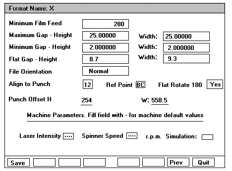
Note: The format name being defined appears in the title of the above form.
Toggle the Align to Punch field to the number of the Punch Format that you require (a number in the range of 1 to 12).
Press Save <F1> to save and exit.
Enter an exposure dialog, for example, Align to Punch Exposure Dialog, on previous page.
In the Format field, type in the format name that you defined in the Format Name form (above).
All the parameters that were defined in the Format Name form for this particular Plotter format are loaded into the exposure dialog.
Note: If you are using Convert & Plot, and the file destination is Plotter, then when you select a format that contains an Align to Punch parameter, this Punch Format is automatically assigned to all the files in this Job.
This section describes the Rotate 180 parameter which appears in the exposure and Plotter Format panels.
The Rotate 180 parameter is one of the three parameters that appear when you activate the Align to Punch option. It enables you to rotate the entire exposed image 180 (when set to Yes). This enables you to orientate the image to the punched holes so that when the film tile is placed on a plate, the images are orientated correctly. The following shows an example of a situation where this parameter is required.
For example: The following diagram demonstrates the need for the Rotate 180 parameter. The first row of diagrams shows what happens when the Rotate 180 parameter is not used. The second row of diagrams shows how Rotate 180 is essential for achieving correct image to punch orientation when using tiles and punch holes.
Rotate 180
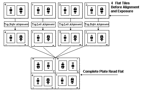
The picture on the left shows a large image that requires 4 tiles.
The center pictures show each part of the image exposed on an image tile. Rotate 180 was not applied in the top center picture, and was applied in the bottom center picture.
The right most pictures show the plate ready flat that results from the placement of these tiles on a plate making machine.
As you can see rotating tiles 1 and 2 is mandatory to achieve correct image to punch orientation.
Select Punch Format <F5> in the exposure dialog to create or modify Punch Formats:
Punch Formats
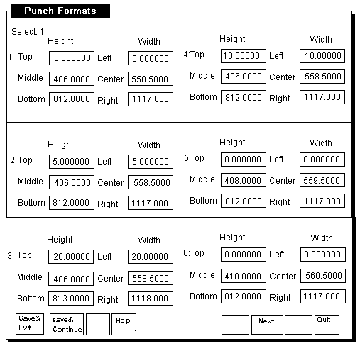
Six formats are shown in each page. Press Next <F6> to view the next page.
Press Help <F4> to view an informative help screen that shows the placement of each position (TL, MC, TR and so on) on film.
Enter a coordinate value in each of the parameters of a Punch Format: Top, Bottom, Left, Right, Middle and Center to define the nine positions on film.
Checking Punch to Center Alignment
Overview
Punch to Center Alignment
The Align to Punch function aligns an image to a pair of alignment coordinates specified in a Punch Format. These coordinates can be defined anywhere on the imageable area on film.
Holes are punched on film by hardware. The position of the hole punchers is determined during installation.
Note: One exception is on the Raystar where the vertical position of the punch holes is determined by software.
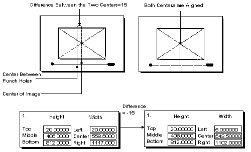
The purpose of the Align to Punch function is to align an image to the punch holes. However, in reality, there is no direct correlation between the punch hole positions (determined by hardware) and the alignment coordinates. When imagesetter hole punchers are installed, there is a chance that they may not be exactly centered to the imageable area on film. There may be a deviation between the center of the exposed image and the center between the punch holes. If this deviation exists, it will cause misalignment between exposed images and the punch holes.
This section describes how to check and adjust your alignment coordinates (in Punch Formats) so that exposed images are aligned correctly in relationship to the punch holes on film.
To check the alignment of an image to punch holes, you must check that a centered image is also centered to the punch holes, as follows:
Find the center of an image exposed in the center of the imageable area on film.
Then compare it with the center between the punch holes.
This section describes how to check whether there is a deviation between these two centers, how to calculate it and how to take this deviation into account when you set the alignment coordinates in a Punch Format.
The procedure described need only be performed once before you start using the Align to Punch feature.
Dolev 200: 358 x 500.
Dolev 400: 642 x 500.
Dolev 800: 812 x 1117 (Large Cassette)
500 x 1117 (Medium Cassette)
Set the Align to Punch option to No in the exposure dialog.
If the center of the image is to the right of the center between the punch holes, then subtract this value.
If the center of the image is to the left of the center between the punch holes, then add this value.
From now on, all exposed images are correctly aligned to the holes punched on film.
Note: When adjusting Punch Format alignment coordinates, note that you can only enter positive values that are not larger than the maximum imageable film area.
For example:
Check Punch to Centered Image Alignment