This document provides explanations and instructions on trouble shooting the most
common errors and failures associated with the new Laser Diode Static Optics:
During the start up cycle of the Dolev800/V an error message appears : No LDT intensity change.
During the Òstart expose' an error message appears : 'Coarse calibration fail'
During the Òstart expose' an error message appears : 'Laser set point error '.
Explanations:
The Laser intensity in the new Static Optics is controlled by means of a motorized
knife which is located inside the Static Optics and sets the Laser intensity by blocking
part of the beam. This knife is controlled by a small stepper motor.
During the start up cycle, the knife moves in and out of the beam path (from minimum to
maximum light blocking position) and during that time the laser light is fed back from the
solar cell positioned on the shutter to the OMC board.
If the OMC board does not detect voltage changes coming from the shutter solar cell -No
LDT intens. change error is generated.
If during start up or before exposure, no light changes are obtained during movement of
the knife while doing coarse calibration, the 'Coarse calibration fail' error
message is generated.
'Laser set pointerror ' is generated during internal
calibration when the machine is not able to bring the diode to the working point. This
part of the calibration does not involve light measurement by the shutter and OMC board.
This calibration is internal to the Static Optics and usually the reason to this failure
is a defective diode (replacement of static optic is required).
Troubleshooting:
Listen to the knife motor in the Static Optics during the calibration. If it makes
ticking noise it means the motor is getting the rotating pulses, if the motor doesn't
move, check the LDR board by running Diag/Drivers/LDR_INT.
Disconnect the fiber cable of the static optics from the chassis. Observe the light
being emitted from the fiber during the laser calibration (being careful not to place
fiber in direct eye contact). The light should ramp up and down. The message no
LDT intens. change or 'Coarse calibration fail' should appear in
messages on the Dolev monitor because no light is being fed back from the shutter.
Re-connect fiber.
Check the following voltages on the shutter amplifier board:
Connect DVM across pin 2 and pin 5 - should be +15V.
Connect DVM across pin 2 and pin 6 - should be - 15V.
Connect a scope probe or DVM across TP-GND and TP-OUT on the shutter amplifier board.
Force the Dolev through a start up cycle or calibrate the light to value of 9000 and
observe signal during laser calibration. The signal should swing between 0v to -15v:
If the voltage is low, 0v to 5v - the shutter might be defective or the shutter light
signal is too weak. The following could be the reasons and possible fixes:
Dirty fiber tips - disconnect and clean fiber connectors.
Dirty fiber tips on the collimation unit - remove shutter and clean the fiber tips.
Static Optics - replace
'LDR_INT' /'FAST LDR _INT' board in standard controller - replace (check the board via
Diag/Drivers - this diagnostic is working correctly)
OMC board - replace
Damaged fiber - order Collimation assy, test externally.
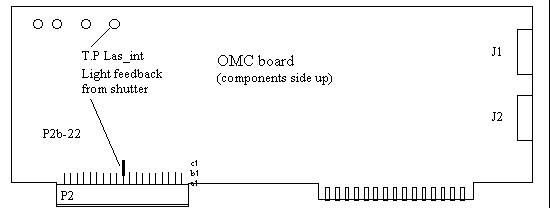
If voltage on the shutter is in the correct range of 0v to -15v, Connect the scope
probe or DVM to TP Las_int on the HOMC board (D800V), or on P2b-22 on the OMC board (D800)
.
Observe the signal during laser calibration. The signal should be the same as on
the shutter, 0v to -15v. This will diagnose the cabling between the shutter and the
standard controller, and the signal as it passes through the standard controller mother
board. The signal is then sampled and processed on the OMC board - The following are
possible results and appropriate fixes:
If the voltage is low - there might be a problem in the path of the light signal:
<> retractive cord <> connector on standard controller - P3 (78 pin conn) pin
57. If needed, order retractive cord FCO 20674 (test external) or replace standard
controller.
If the voltage is in range - possibly bad OMC board - replace.
General Testing
The best way to test the complete mechanism and the sequence of the light calibration is
via the tools utility (not the diagnostics). Use the monitor or the panel.
Calibrate the light to the values of 300, 3000, 9000 and check for 'pass'.
Use the above for troubleshooting any failure of light calibration.
Use the Diag/Drivers to check the functionality of the LDR_INT boards (the results are
100% correct and reliable).
Due to a bug that we have on Ver 5.61 / Ver 5.52 and below, the Intensity Strips may
fail. - In this case do not replace any unit unless you get the same problems during
regular exposure.
Comment:
The only diagnostics referred to in this note is the Diag - Drivers - LDR I/F.
All other Static Optics diagnostics should be used for reference only. The
final confirmation of the functionality of the Static Optics is by real exposure
operation.