Home | Contact Us | Submit Troubleshooting Info | Search | Help
Output | Software Solutions | Proofing | Color, Screening and Calibration | Scanning | Digital Photography | Consumables | POS
Home | Contact Us | Submit Troubleshooting Info | Search | Help
Output | Software Solutions | Proofing | Color, Screening and Calibration | Scanning | Digital Photography | Consumables | POS
An oscilloscope is needed when replacing or aligning an encoder assembly. This page contains information about the two oscilloscopes most commonly used by Creo Customer Support.
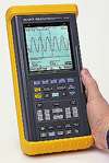
Fluke 99B Scopemeter
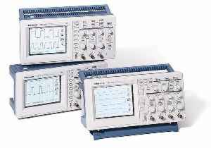
Tektronix TDS 200 series
Tips on using them: Oscilloscope selection | Tips and techniques
High bandwidth is not a requirement for an oscilloscope being used to align encoders. The frequency of the analog signals A+, A-, B+, and B-, are only 27 kHz when the drum is spinning at 180 rpm! An oscilloscope with a bandwidth of only 20 MHz is more than enough for encoder alignment. A 100 MHz oscilloscope will be no better for this task, and it costs significantly more.
Triggering is quite important. Some inexpensive oscilloscopes do not do triggering very well, making encoder alignment almost impossible.
Digital storage scopes are better than analog scopes for viewing the index pulse. There will only be 3 index pulses per second from a drum spinning at 180 rpm, so it is difficult to see it with an analog scope.
These scopes, which are portable with LCD displays, are easy to use and relatively inexpensive. The controls are very similar to Tektronix CRT scopes, so if you have had experience with analog oscilloscopes, you can learn to use this one quickly.
More information on these oscilloscopes is available on the Tektronix web site.
This model is also good for encoder alignment. It has more features than the Tektronix scope, but is expensive and more difficult to use. Earlier models were 50 MHz; newer ones have a bandwidth of 100 MHz.
More information on these oscilloscopes can be found on the Fluke web site.