Home | Contact Us | Submit Troubleshooting Info | Search | Help
Output | Software Solutions | Proofing | Color, Screening and Calibration | Scanning | Digital Photography | Consumables | POS
Home | Contact Us | Submit Troubleshooting Info | Search | Help
Output | Software Solutions | Proofing | Color, Screening and Calibration | Scanning | Digital Photography | Consumables | POS
The purpose of this FCO is to solve registration problems of plates
that are more than 550 mm wide. In addition, the Head Spoilers with 8 mm pins
will be replaced with 12 mm Spoilers.
The gap between the drum and the spoilers was reduced at all the six spoilers
to have good attachment of 0.15 mm plates.
The procedure includes the following steps:
The FCO includes the following:
| Cat. Number | Quantity | Part Name |
| 290A2R947 | 4 | 12MM PIN |
| 290A8L444A | 1 | HEAD WINDSHILD 4 |
| 290A8L445A | 1 | HEAD WINDSHILD-R |
| 290A8L446A | 1 | HEAD WINDSHILD-L |
| 290A8L448A | 1 | HEAD WINDSHILD |
| 290A8L449A | 1 | HEAD WINDSHILD-CR |
| 291B2R946A | 1 | HEAD SPOILER 5 |
| 380A05041 | 4 | SOC HD CAP STST 8-32*3/8" |
| 380A05061 | 12 | SOC HD CAP STST10-24*1/2" |
| 382D11000 | 12 | SPRING L/W ST ST #8 |
| 480C10190 | 1 | ADHESIVE,RETAIN.LOC. 242 |
| 480C44510 | 1 | SILICONE AP BLACK 90 ML |
Note: To adjust the two inner spoilers you need a 400 mm ruler.
Replacing all head spoilers with the new ones
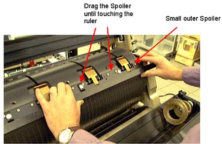
Verifying image parallelism for large plates
1. Load a plate on the machine, minimum width of 550 mm.
2. Expose a strip file of maximum width with a margin of 20 mm.
3. Measure the distance between the exposed file and the edge of the plate on
both sides of the plate.
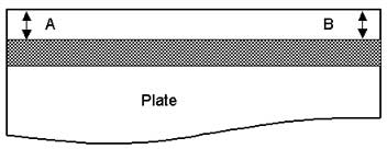
4. Verify that the difference between the two measurements (A and B) is not
greater than 0.1 mm.
5. If the difference is more than 0.1 mm, you need to adjust the two outer spoilers
(see Adjusting the Spoilers).
Verifying image parallelism for small plates
1. Load a plate on the machine, maximum width of 550 mm.
2. Expose a strip file of maximum width with a margin of 20 mm.
3. Measure the distance between the exposed file and the edge of the plate on
both sides of the plate.
4. Verify that the difference between the two measurements (A and B) is not
greater than 0.1 mm.
5. If the difference is more than 0.1 mm, you need to adjust the two inner spoilers
(see Adjusting the Spoilers).
Adjusting the Spoilers
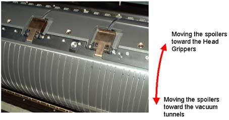
1. Select A or B, whichever is bigger, and move spoiler on that side slightly
towards the Head Grippers (away from the vacuum tunnels) by opening the spoiler
screws.
2. Tighten the spoiler and re-expose the same file.
3. Recheck the differences between A and B.
Repeat this procedure until you get a maximum tolerance of 0.1 mm.
Attaching RTV to the Spoilers
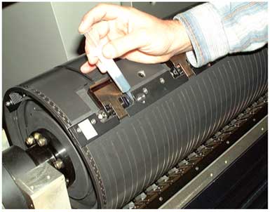
Attach the RTV to the back side of the spoiler on both sides of the spoiler
(on the curved side), as shown in the figure below.