

Home | Contact Us | Submit Troubleshooting Info | Search | Help
Output | Software Solutions | Proofing | Color, Screening and Calibration | Scanning | Digital Photography | Consumables | POS
Home | Contact Us | Submit Troubleshooting Info | Search | Help
Output | Software Solutions | Proofing | Color, Screening and Calibration | Scanning | Digital Photography | Consumables | POS
Available in pdf format
Description : This PM is to replace the Mother Board and the Daughter Board against condensation leading to a possible short within the L Box.
|
Prepared By: Yaron Soffer |
FCO Kit No: 510F27936 & 510F27936A |
|
Comp. Level: |
Machine S/N: 84209 (first machine with coated boards) |
|
Catalog No: |
S/W Affected: No |
| Type of Change: PM Mandatory |
Total Number of Pages: 12 |
|
Product Mgr: Nir Halup |
Approval Date: 15 Nov 2001 |
|
Product Support: Yaron Soffer |
Approval Date:15 Nov 2001 |
| Customer Support Mgr: Assaf Zach | Approval Date: 15 Nov 2001 |
|
Estimated time to implement: |
24 Diode L-Box: 3 hours |
TIPS
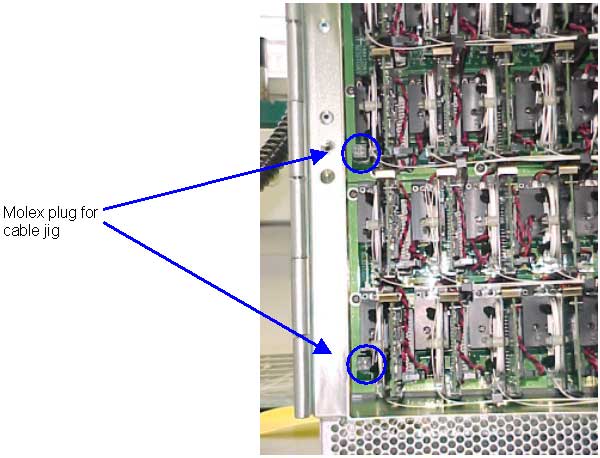
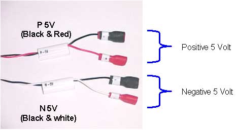
Using the cable Jig
The cable jig is connected to the Molex plug located on the left-lower side
of each Daughter Board.
Hardware procedure:
This is an overview of the FCO, the full detail procedure is describes step by step in the movie:
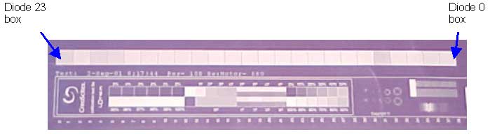
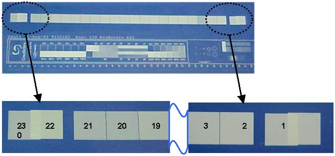
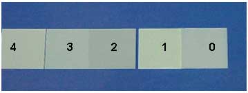
- Perform the Uniformity test as explained in the Test procedure below.
- Label the Diode housings 0 to 24 (0-48 for 48 diodes)
- See Notes to CD number 1.- Remove the Mother board and the ground wire attaching the motherboard to the Daughter boards
- see Notes to CD number 2- Remove each of the diode housings along with their LDD boards and laser diodes.
- See Notes to CD number 3.- Place the LDD boards and laser diodes on the matt.
- See Notes to CD number 4.- Remove the supporting arm brackets from the daughter boards.
- See Notes to CD number 5- Disconnect the ground cables.
- Remove the existing daughter boards.
- See Notes to CD number 6.- Insert the new daughter boards.
- Connect the ground cables.
- See Notes to CD number 7- Insert the supporting arm brackets on the daughter boards.
- See Notes to CD number 5- Reinstall the diode housings along with their LDD boards and laser diodes.
- Insert the new Mother board.
- Stick "C" label on the L-Box and on the Distribution Box near the machine serial number.
- Perform the Test procedure.
- Send the report form.
Notes to CD movie:
- Place a label on each one of the LDD according to the
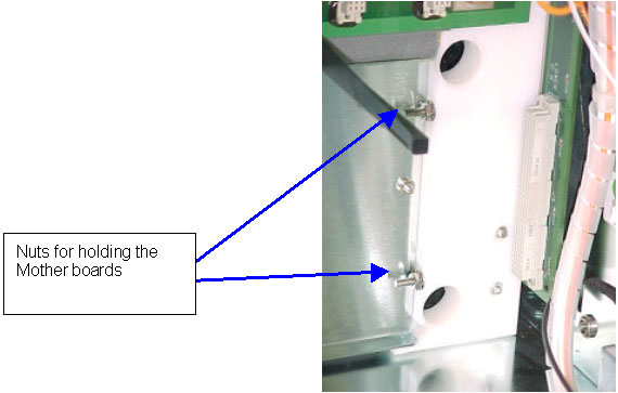
- When taking out the Mother Board use two keys to open two nuts, do not remove the entire screws.
In 24 diodes L-Box, two of the screws are tighten with nuts (as shown bellow). The other upper screws are connected to the diode metal base.In 48 diodes L-Box are attached to the metal base.
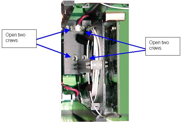
Each of the diode housings (LDD boards and laser diodes), have four screws (you have to remove the boards and the bracket together)
In the CD it is shown that an antistatic bag is used to place the boards but with every FCO kit a conduct matt is splayed to replace thus bags. On the 24-diode laser box, the laser diodes can be placed inside the L-Box on top of the antistatic matt.
- In the 48 diodes L-Box only the bottom Support brackets are facing down while the other are facing up.
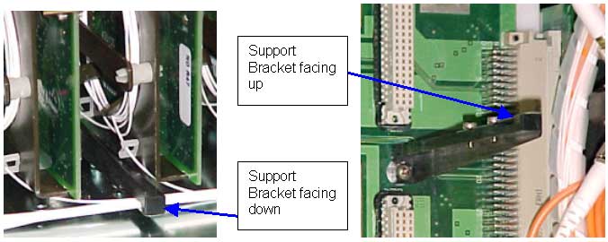
- To remove the Daughter Bard:
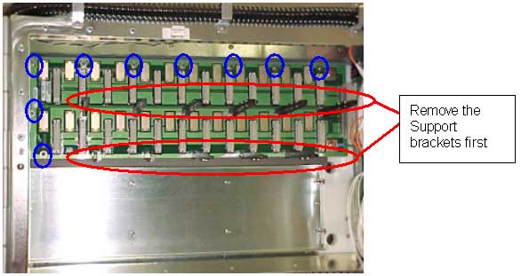
- Remove the support brackets located bellow the LDDs.
- Remove the screws around the Mother Board.
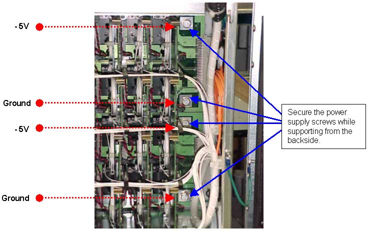
- When tightening the power supply screws in the Daughter Boards place an open key 7/16th inch socket wrench on the back side, to ensure tight close.
| PART | QTY | Description |
| 395A10006 | 1 | Philips Screw Driver |
| 503D1C063S | 1 | Mother Board |
| 503D1C065 | 1 (2 for 48 Diode L-Box) | Daughter Board 2 |
| 504L3E929 | 1 | Cable Jig for Power Supply measurement |
| 501V1R750 | 1 | CD Movie |
| 1 | Set of labels | |
| 395E00031, 395E00032, 395E00033 | 1 | Antistatic matt with ground cable |
| 395A10105 | 1 | SOCKET WRENCH 1/4"x7/16" |
Appendix A - Status Report - Lotem L-Box PM Procedure for Mother and Daughter Board replacement
Appendix B
Script for FCO 510F27936 & 510F27936A
Replacement of Mother and Daughter Boards in Lotem Plate setters.
You are about to see a demonstration of the procedure for replacing old Mother and Daughter boards in Lotem Platesetter. This mandatory FCO is required in order to provide enhanced safeguards against condensation leading to a possible short within the L Box. Replacement of the Mother and Daughter boards requires you to remove and put back all the diode brackets along with their LDD boards and diodes. The procedure is the same for 24 and 48 diode L boxes. It is not complex though it is tedious and requires care in its implementation.
Prior to starting the FCO, you will need to have the following tools handy.
The FCO kit consists of
A new motherboard and one or two daughter boards (24 or 48 diodes).,
Two antistatic bags, grounding wires, a Phillips #0 screwdriver, and a set of
numbered labels..
Let us also have a look at an old and a new motherboard before we begin the procedure. Note the shiny waterproof surface on the new motherboard.
An overview of the FCO looks like this.
Now lets look at the procedure in detail.
Before starting the procedure make sure the power is off.
Open the L Box with a #2 Phillips screwdriver. The door is hinged and held closed
by a single screw.
Put on an antistatic bracelet wired to the L Box chassis.
Remove the cover from the motherboard.
Remove the four screws holding the motherboard in place using the socket wrench with the 5/16th inch socket. Remove the ground wires leading to the Daughter boards. Note that these long shaft machine screws need only to be loosened. They do not have to be removed. Do not remove the Motherboard yet.
Turn the Motherboard to the other side..
Remove the Molex connector and then remove the two flat cable connectors.
Note that the lower flat cable connector came from the slot marked "Lotem"
when TSP was installed or from the slot marked "DOP" when VLSI was
installed.
Now you can remove the Motherboard.
Open the L Box with a #2 Phillips screwdriver. The door is hinged and held closed by a single screw.
Lay an antistatic bag flat on the floor in front of the open L box.
Attach antistatic wires between the bag and chassis with alligator clips.
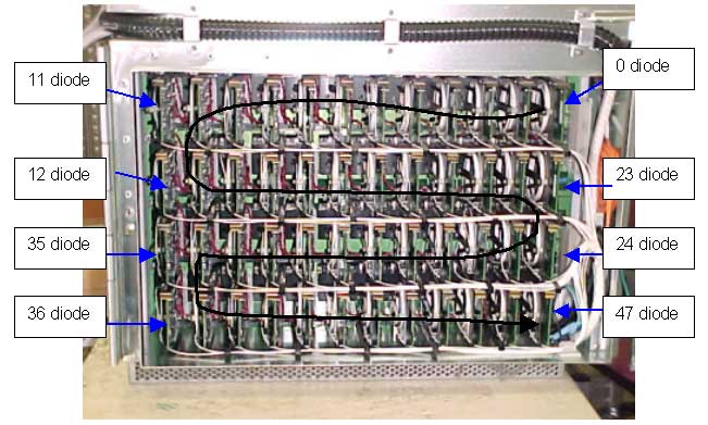
Note carefully the positions of the diodes beginning with diode 0 and ending
with diode 47 for 48 diode machines or 23 for 24 diode machines.
You are now going to place labels on each of the diode housings corresponding to their software designations from 0 to 23 or 0 to 47. Be careful not to be confused by the printed labels on the inner part of the diode-housing going from 1 to 24. Ignore these printed labels.
Begin attaching the supplied numbered stickers to the black diode housings starting with diode 0. Be sure to follow the numbering sequence going from right to left on the top row ( 0 to 11), then left to right on the second row (12 to 23). For 48 beam machines, continue from right to left on the third row (24 to 35) and finally left to right on the bottom row (36 to 47).
Be careful not to allow any fiber cables to get caught under the stickers.
Now begin to remove the diode housings with LDDs and diodes attached. Begin with the last diode housing 47 or 23. Do not separate the LDDs from their housings. Use the Phillips #0 screwdriver to remove the four screws holding each diode housing in place. Note the positions of these four screws. Be careful not to damage any fibers when removing these screws. You may have to slightly move one or more of the fibers out of the way in order to get at the screws.
Unwind a sufficient amount of fiber cable from the diode housing so you can lay the diode housing down neatly on the antistatic bag.
Place the diode housing with LDD attached carefully on the antistatic bag lying on the floor. You need to put each diode housing down in a cascading arrangement. This arrangement must follow the same order as the mounted diode housings on the daughter board.
Loosen the fiber bundle from the channels on the supporting arms so you can free the diode housing from the chassis.
Repeat the process for each diode housing working in reverse order to the diode numbering. Start with diode 47 in 48 beam machines or diode 23 in 24 beam machines.
Be careful not to tangle the fiber cables as you lay them down.
See here how the diode housings have been cascaded on the anti static bag.
If you are working on a 48-diode machine as seen here, place the bottom 24 diodes on the antistatic bag first. Then place another antistatic bag over this arrangement and position the top 24 diodes on the second antistatic bag making a second layer.
Remove each of the fiber cable support brackets using a Phillips #2 screwdriver. Note the position of the screws on the support brackets.
Remove the remaining screws holding the daughter boards to the chassis using
the #2 Phillips screwdriver.
Remove the remaining screws containing ground wires using the 7/16th inch socket
wrench. These wires were attached to the Motherboard.
Once all the screws have been removed, grab the daughter board by a connecter
on both sides and pull it out from the chassis.
Now you are ready to install the new Daughter and Motherboards.
First insert the new Daughter boards into the chassis. Just press them into place.
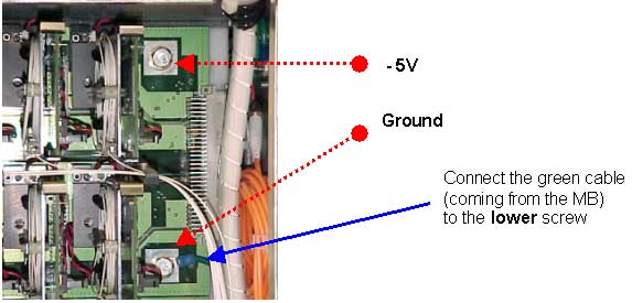
Insert the four screws (Two screws for 24 beam machines) using the 7/16th inch socket wrench with ground wires attached on the bottom right side of each daughter board. Insert the screws by hand. Do not tighten them with the screwdriver yet.
Insert the mounting screws on the left side of the daughter boards using a #2 Phillips screwdriver.
Follow this by inserting screws along the top row of the daughter boards. Be sure to insert each screw with a flat washer and a lock washer.
On the top of the second row, attach the fiber cable support brackets into their positions. Note the orientation of the fiber cable support brackets. On this row, the fiber cable support brackets face down. Do the final tightening of the brackets by rotating the bracket with the screw for about half a turn.
Insert the fiber cable support brackets in the lowest row. Note that in this row, the fiber cable support brackets face up.
Reinsert the diode housings one by one starting with diode number zero. Rewind some cable into the diode housing before insertion to take up the slack. Tighten the four screws attaching the diode housing to the daughter board using a #0 Phillips screwdriver.
Be sure to check that each diode housing is mounted securely.
As you proceed with one diode housing after another, arrange the fiber cables neatly in the fiber cable support bracket channels.
Keep the fiber cables free of any snags and arrange them neatly.
Also place the fiber bundles neatly in the plastic cable clamp on the right side of the board.
Once you have reinserted all the diode housings, recheck to see that all diode housings and LDDs are seated tightly.
Attach the Molex, upper flat cable and then the Lotem(TSP) cable to the Motherboard before inserting the board.
Attach the ground wires, coming from the daughter boards, to the back of the motherboard using the 5/16th in screws. Tighten only by hand.
Now gently press the Motherboard into place and tighten the screws with the 5/16th inch socket wrench.
Replace the cover over the Motherboard.
Insert two stickers labelled "C". Place one on the existing L box
serial number label. Place the other "C" label next to the power switches.
The C stands for "Coated" showing that the L box contains moisture
resistant boards.
The FCO is now complete.
Appendix C
L-Box Parts list:
| PART | QTY 24/48 | Description |
| 209A00120 | 1 | P/S SWITCHING 12V/27A (24 Diode L-Box) |
| 209A00130 | 1 | P/S SWITCHING 5V/60A (24 Diode L-Box) |
| 209A05302 | 1 | P/S WIDE R. 5V/30A W/PWR FACT. (24 & 48 diode L-Box) |
| 209A10905 | 1 | P.S. 5V 600W W/PWR FACTOR (48 Diodes L-Box) |
| 209A11020 | 1 | P/S 12V 600W W/PWR FACTOR (48 Diodes L-Box) |
| 291F5L908 | 12/24 | OP FIBER SUPPORT |
| 295A82314 | 24/48 | Diode & Fiber Holder |
| 503B2L028S | 24/48 | LDD |
| 503B2L560S | 24/48 | LDD2 |
| 503C2L033S | 0/1 | TEC CONTROLLER BRD ASSY (only for 48 diode) |
| 503C2L738S | 1/0 | Tec 24 control (only for 24 diode) |
| 503D2L153S | 1 | DDB-1 |
| 503D2L695S | 1 | DDB-1-N |
| 504L1L639 | 1 | HEAD RESOLUTION CABLE. |
| 504L1L640 | 1 | HEAD FOCUS CABLE. |
| 504L3D098 | 24/48 | LDD2 CABLE L=0.18M |
| 504T1L472 | 1 | Flat cable is in all L-Boxes (TSP & VLSI). From MB to DDB-1-N |
| 504T1L473 | 1 | For VLSI configuration: from "DOP" connection to J7, single ribbon |
| 504T2D064 | 1 | For TSP configuration: from "Lotem" connection to J7+J8, double ribbon |
| 505B2D349 | 1 | EDGE DET.ASSY |
| 510P1N220 | L-Box & Pack 48 diodes | |
| 510P1R026 | L-Box & Pack 24 diodes | |
| 613A00021 | Laser Diode |