

Home | Contact Us | Submit Troubleshooting Info | Search | Help
Output | Software Solutions | Proofing | Color, Screening and Calibration | Scanning | Digital Photography | Consumables | POS
Home | Contact Us | Submit Troubleshooting Info | Search | Help
Output | Software Solutions | Proofing | Color, Screening and Calibration | Scanning | Digital Photography | Consumables | POS
Description : Replace aluminium X and Y loading system shafts with stainless steel shafts.
|
Prepared By: Dennis Kaliser |
FCO Kit No: 510F27946 |
|
Comp. Level: NA |
Machine S/N: |
|
Catalog No: NA |
S/W Affected: |
| Type of Change: conditional |
Total Number of Pages: |
|
Product Mgr: Yehoda Solomon |
Approval Date: 24.03.02 |
|
Product Support: Mario Amir |
Approval Date: |
| Product Support Mgr: Haim Vaknin | Approval Date: |
| Open the front cover of the MCU followed by the side covers and top coverTurn the power off. | 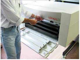 |
| Loosen tension on the X and Y belts. First loosen and remove the tension screws with a ¼" Allen. Then insert and tighten the 6/32" x 1" retaining screws to compress the springs. These two belts should now be loose. | 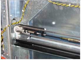 |
| Go to the left side of the machine. | |
| Loosen the screws on the bracket holding the Y motor so as to loosen the small Y motor belt. There are three screws to loosen, one from the top and two from the side. When you loosen these screws, the bracket will pivot on the center screw. | 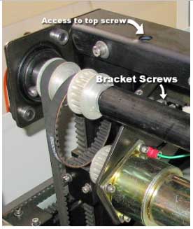 |
| Loosen the coupling for the bearing on the left side of the Y shaft. Do not remove the coupling | 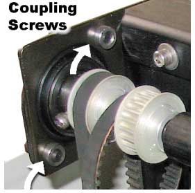 |
| Loosen the setscrews holding the bearing to the shaft using a 5/32" Allen. | 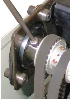 |
| Go to the right side of the machine | |
| Loosen and remove the coupling and bearing on the right side of the Y shaft. | 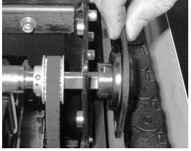 |
| Pull the shaft out of the machine being careful to maintain the relative position of the belts. The coupling with bearing on the left side will remain on the machine. | |
| Start to insert the new Y Shaft. Note that the Y shaft is the shorter of the two shafts supplied in the kit.Also note the orientation of the two pulleys on the left side and single pulley on the right side.Insert the Y shaft through the belts in the proper order. | |
| Continue the shaft insertion by placing it in the left bearing so that the hole in the flat side of the shaft end aligns with the threaded hole in the bearing.Put the three loose belts back in place on their respective pulleys | 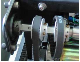 |
| Replace the bearing and coupling on the right side.Note that the setscrew side of the right pulley faces inside the machine.Reinsert the four screws with washers holding the right coupling in place. Be sure to use the special screws supplied for this purpose. The ends of these screws are thread less. Do not tighten them yet. | 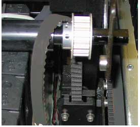 |
| Place Locktight 638 on all the setscrews. Do not tighten them yet. | |
| Go to the left side of the machine. | |
| Recheck to see that the hole in one of the two flat sides of the shaft end aligns with the threaded hole in the bearing. Make sure the second threaded hole in the bearing aligns with the other flat side of the shaft end.Tighten the setscrews. | 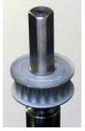 |
| Go to the right sideCheck that the flat sides of the shaft end align with the threaded hole in the bearing. Insert and tighten the setscrews. | |
| Tighten the bearing coupling on both sides. | |
| Stage IIAdjust parallelism of the Y axis to the Cassette frame and return tension to the belts. | |
| Pull the top cassette out. | 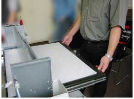 |
| Lower the XY bar by hand until it contacts the frame on both sides. Be sure to have firm contact. | 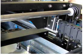 |
| Remove the retaining (compression screws) from the left and right belt assemblies. Reinsert the tension screws. Tighten them approx ½ turn after contact with the spring. Check the belt tension by hand. Close the locking nut on the tension screws. | 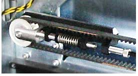 |
| Close the top screw for the small motor belt tension and then check the belt tension with a belt tension jig. | 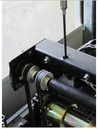 |
| Tighten the screws holding the Y motor to the frame. | 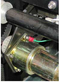 |
| Rotate the Y shaft up and down by hand. Check to see that the bar touches the frame firmly on both sides at the same time. | 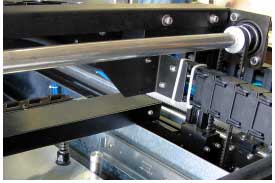 |
| If good contact is made, the procedure for the Y shaft is complete. | |
| If not, continue as follows: | |
| Use a 7/64" Allen to open the four bolts on both sides of the Y belt locker. | 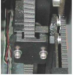 |
| Push the XY bar down hard on both sides so that they touch the frame firmly. Re-tighten all four screws. | 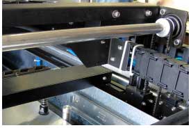 |
| Follow the same procedure for the X shaft substituting positions as appropriate. | |
| You will need an L Allen to loosen the bearing coupling because the side frame is in the way. | 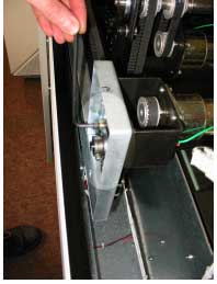 |
| Remember to loosen the belt tension first and then the bearings.Note that loosening the tension on the X motor belt requires complete removal of the X motor. | |
| PART | QTY |
| 507F2D961 | 1 |
| 507F2D970 | 1 |
| 358E55000 | 4 |
| 380S05014 | 6 |
| 290A9L928 | 2 |