Home | Contact Us | Submit Troubleshooting Info | Search | Help
Output | Software Solutions | Proofing | Color, Screening and Calibration | Scanning | Digital Photography | Consumables | POS
Home | Contact Us | Submit Troubleshooting Info | Search | Help
Output | Software Solutions | Proofing | Color, Screening and Calibration | Scanning | Digital Photography | Consumables | POS
Description Vacuum Hose Replacement
|
Prepared By: Haim Vaknin |
FCO Kit No: 510F28032 |
|
Comp. Level: |
Machine S/N: |
|
Catalog No: |
S/W Affected: |
|
Type of Change: Mandatory |
Total Number of Pages: 7 |
|
Product Mgr: Yehuda Solomon |
Approval Date: |
|
Product Support: Haim Vaknin |
Approval Date: 31-Oct-2001 |
|
Customer Support Mgr: Assaf Zach |
Approval Date: |
Reason For Change
The new and improved vacuum hose increases reliability.
Description of Change
The following items are replaced:
Change Procedure
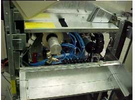
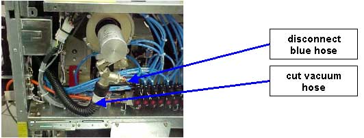
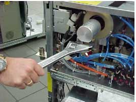
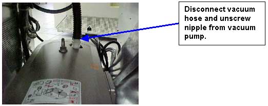
To assemble the new vacuum hose, you must first disassemble the old one.
Disassemble
Assembly
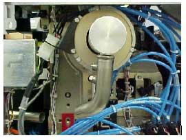
1. Make sure that the new swivel interface thread has Teflon on it.
2. Screw the new swivel interface onto the swivel. The swivel interface should
be 35-45 degrees to the left of the swivel as shown in the following picture.
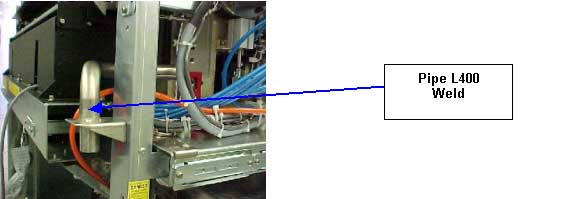
3. Replace the new pipe L400-weld using the screws from the old adaptor.
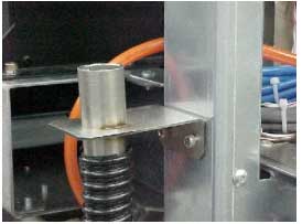
Note: If the machine includes the MCU, use the existing vacuum tube weldment (296A2T694), as shown below.
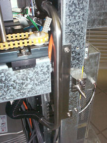
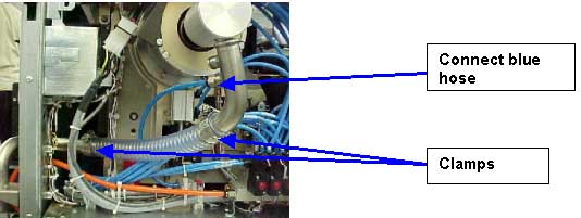
4. Cut a length of vacuum hose of about 30cm and, using the clamps, connect it to the swivel interface on one side and the Pipe L400-weld on the other side.
5. Connect the blue hose to the swivel interface. (Check the required length
first and cut extra hose.)
6. Replace the light cover using the 4 screws.
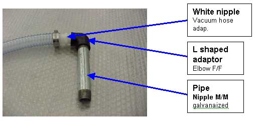
7. Connect the white nipple to one end of the L shaped adaptor using Teflon,
and connect the pipe to the other end of the L shaped adaptor, as shown in the
following picture.
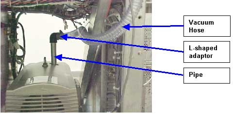
8. Connect the new vacuum hose adaptor (white nipple, L-shaped adaptor, and
pipe) to the vacuum pump.
9. Connect the new vacuum hose about 70cm between the white nipple and the Pipe
L400-weld using clamps.
10. Close the light cover.
11. Close right side door.
Test Procedure
1. Power up the machine and start the application.
2. Place the cheater on the open door.
3. Using the application, open the drum vacuum pump and activate the vacuum
pump.
4. Check the hose and hose connections for any vacuum leakage.
5. Power off the drum vacuum pump.
6. Load and expose plates of different sizes and thickness, process the plates,
and check for any attachment problems on the plates.
Parts List
The following parts are included in the FCO kit. (Under the 510F28032)
| PART | DESCRIPTION | QTY |
| Vacum hose adap. | 290F7B216 | 1 |
| Niple M/MGalvanaized | 291A7B368 | 1 |
| Elbow F/F 3/4xnptTo 3/4 npt | 344C34000 | 1 |
| Swivel pipe assy | 507A3E623 | 1 |
| Vacuum hose | 344F43510 | 2 |
| Pipe L400 weld | 291A6B372 | 1 |
| Clamps | 388B16020 | 4 |
| Packing Lable-WHT | 374A00080 | 1 |
| FCO Document | 7!FCO-DOC | 1 |
|
Teflon 1 |
507A3E603 | 1 |
Attached Documentation
None.
Material Disposition
Dispose of the old parts.
Logistics
|
CSTA |
: |
50 |
|
CSTE |
: |
120 |
| CSAP | : | 5 |
|
CSN |
: |
5 |
|
CSMA |
: |
5 |
| Other | : | |
| No Limit | : |
| D.U | Month | QTY | Month | QTY | Month | QTY | |
| CSTA | : | 20 | 15 | 15 | |||
| CSTE | : | 40 | 40 | 40 | |||
| CSTP | : | 5 | |||||
| CSTN | : | 5 | |||||
| CSTMA | : | 5 | |||||
| Other | : |
7.3 Inventory in warehouses:
None.