Home | Contact Us | Submit Troubleshooting Info | Search | Help
Output | Software Solutions | Proofing | Color, Screening and Calibration | Scanning | Digital Photography | Consumables | POS
Home | Contact Us | Submit Troubleshooting Info | Search | Help
Output | Software Solutions | Proofing | Color, Screening and Calibration | Scanning | Digital Photography | Consumables | POS
Applies to |
Lotem®
400 platesetters:
|
Priority = Next failure |
|||||||||||||||||
Component |
Gripper actuator guide |
||||||||||||||||||
Problem |
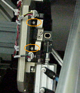
Uneven gripper movement prevents one side of the gripper from reaching the detector. This happens when the gripper bearing loosens and falls off due to repeated collisions with the edges of the slot in the gripper actuator guide. |
||||||||||||||||||
Solution |
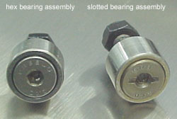
Remove the four gripper actuator guides and replace them with guides that have a longer slot (part number 290B8L596A). The design of the replacement guide prevents the gripper bearing from hitting the edges of the slot. In addition, replace the slotted bearing assembly with the hex bearing assembly to enable better tightening of the bearing assembly and thus prevent the bearing from falling off. | ||||||||||||||||||
Time needed to implement |
2-3 hours |
||||||||||||||||||
Parts needed |
|
||||||||||||||||||
Special Tools needed |
10 mm open wrench | ||||||||||||||||||
Procedure |
This procedure includes the following sections:
Replacing the gripper actuator guide
Note: Perform the following steps on the upper and lower gripper actuators guides on each side of the machine (four in total).
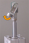
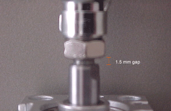
Note: Do not reassemble the piston lock yet. Adjusting the piston activatorYou must adjust the piston activators to work with the new gripper actuator guide. To prevent the drum from becoming stuck, readjust the piston activators to obtain a 1.5 mm gap between the nut and the piston.
|
||||||||||||||||||
Test |
|
||||||||||||||||||
Logistics |
Approved quantities:
| ||||||||||||||||||
Material Disposition |
Dispose of old activator guide (P/N 290B8L596) |
||||||||||||||||||
Document number |
719-29071 Rev B | ||||||||||||||||||
Technical contact |
Product Support Manager: Haim Vaknin |
||||||||||||||||||
Date submitted |
28 Aug 2002 | ||||||||||||||||||

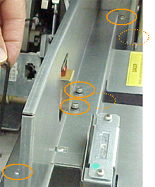
Remove the six Allen screws from each bridge, and then remove the bridges.