Home | Contact Us | Submit Troubleshooting Info | Search | Help


    Output | Software Solutions | Proofing | Color, Screening and Calibration | Scanning | Digital Photography | Consumables | POS


FCO 512-00106B - Load Roller Bar L400

Applies to

  Lotem® 400 platesetters:
  • Lotem 400
  • Lotem 400 (small)
  • Lotem 400 Xpose
  • Lotem 400 w/MCU
  • Lotem 400 Quantum

Priority = Next failure
Release date = 19 Mar 2003

Component


Load roller bar and springs

Problem


Rollers on the load roller bar slipped off their springs.

Solution

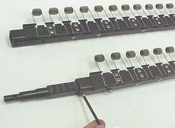
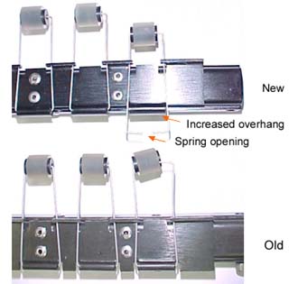
  The load roller bar was redesigned so that the part holding the springs has a larger overhang to keep the springs in place, and the open side of the spring is at the base (and not in the roller) to prevent the rollers from slipping off.
Time needed to implement


1 hour

Parts needed


Part number

Qty

Part Name

290A9C299
25 Drum roller assembly type II
298A9L203A 1 Rollers rod L400
719-00106B rev D 1 FCO document

Procedure


Note: Make sure to use Loctite on all screws.

Removing the load roller bar
  1. In Lotem Controller, open the top door, and then open the side doors.
  2. Turn off the air pressure.
  3. Shut down Lotem Controller and turn off the platesetter.
  4. Disconnect the main power supply.
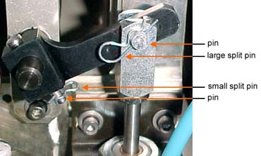
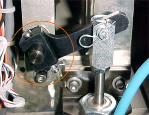
  5. On the right side of the machine, remove the roller arm by removing both split pins and pins, as shown below.
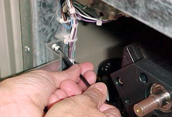
  6. On the left side of the machine, remove the two hex screws from the local 3 box and lift the local 3 box up and out.
  7. To enable access, on each side of the bracket, remove the hex screws, and then slightly lower the bracket.
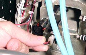
  8. Disconnect the load roller home position (HP) connector.
  9. Mark the location of the roller assembly holder so that you can return it later to the exact position.
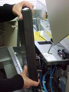
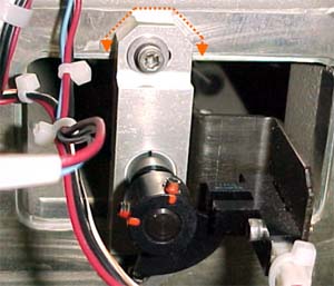
  10. Remove the two hex screws that secure the load roller assembly and then pull out the load roller assembly.
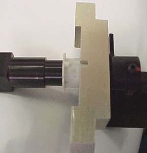
    Note: Make sure that the plastic cap does not fall into the machine, and that the rollers do not fall off.

  11. Open the two end screws on each side of the old load roller assembly and transfer the shafts on both sides of the load roller assembly to the new load roller assembly.
Installing the load roller bar
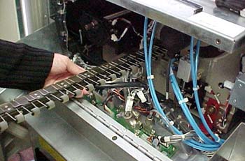
  1. On the left side of the machine, thread the new load roller assembly into the machine, making sure that the springs do not get caught on any wires or cables inside.
    Note: Make sure that the plastic cap, shown in step 10 above, is well mounted in the groove, so that it does not fall into the machine, and make sure that the rollers do not fall off.
  2. With the load roller assembly resting inside the machine, on the left side, slightly tighten one screw to stabilize the assembly.
  3. On the right side, insert and lower the roller arm, insert the arm pin, and then secure it with the small split pin.
  4. Insert the piston pin through the piston arm and the roller arm, and secure it with the large split pin.
    Note: Do not insert the split pin all the way.
  5. Install the load roller HP connector.
  6. Close the bracket and tighten the hex screws that you removed in step 7, above.
  7. On the left side of the machine, install the local 3 box in the local 3 mother board and tighten the two hex screws that you removed in step 6.

Important: Use only short screws to close the local 3 box, as long screws can cause a short circuit.

  1. Connect the main power supply.
  2. Turn on the platesetter and start Lotem Controller.
  3. Turn on the air pressure.
Logistics
CSC Qty
CAM 20
CEU 35
CAP 5
CJP 3
CMA 3

Test


Load a plate and verify that the rollers are attached to the plate. Verify that there are no roller pressure marks after plate processing.

Material Disposition


Dispose of the old load roller assembly.


Document number
  719-00106B Rev D
Technical contact
 

Mario Amir

Product Support Manager: Haim Vaknin

Date submitted
  19 Mar 2003

Popups / Tool Tips for this Page