Applies to
|
|
Platesetters with "old" mainframe:
- Lotem® 400
- Lotem 400 Xpose
- ThermoFlex® Narrow
|
Priority = Next visit
Release date = 09 Apr 2003
|
Component
|
|
Upper rear door "Lift O Mat"
Note: In the following procedure, "upper rear door"
refers to the upper rear door of the Lotem 400 platesetter, or the upper
door of the ThermoFlex Narrow platesetter.
|
Problem
|
|
The upper rear door does not stay open, because the piston is too weak
to support the door.
|
Solution
|
|
Install the redesigned Lift O Mat,
which has a stronger piston (400N instead of 125N) to support and hold the
upper rear door open. |
Time needed to implement
|
|
1 hour
|
Parts needed
|
|
|
Part number
|
Qty |
Part Name
|
252-00794A
|
4 |
Lift O Mat spacer |
| 290A2S226 |
2 |
Top springs axis |
| 290A5A189 |
2 |
Top springs bracket (400N) |
| 290A5A190 |
4 |
Spacer D (400N) |
| 290A5A191 |
2 |
Top spring axis (400N) |
| 347K11139 |
2 |
Gas SP L=365 STR=140 F=400N |
| 385U51110 |
4 |
Hitch pin int D=0.062" L=1-5/6" |
| 719-27688 |
1 |
L400 top door "Lift O Mat" FCO document |
|
Procedure
|
|
Removing the piston assembly:
- Access the piston:
- Lotem 400in Controller, open the upper door, and then open
the upper rear door.
- ThermoFlex Narrowin Controller, open the upper door.
- Turn off the air pressure.
- Quit Controller and turn off the platesetter.
- Disconnect the main power supply.
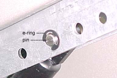
- Disconnect the piston from each piston bracket on the upper door by
removing the e-ring from the piston bracket, and then removing the pin,
as shown below.
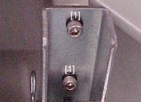
- Remove the six hex screws from each bracket on the upper rear door,
and then remove the bracket.

- Disconnect the piston from each bracket on the mainframe by removing
the e-ring from the bracket, and then removing the pin.
Installing the L400 front door Lift O Mat (piston):
- Install a bracket (290A5A189) on each side of the upper rear door
with the hex screws that you removed in step 6, above.
- Connect the wide side of each piston (347K11139) to the brackets on
the upper rear door:
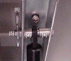
- From the outside of the bracket, insert a spacer (290A5A190) through
each hole, as shown below [4].
- Insert a pin (290A5A191) through the spacers and the hole on the
wide side of the piston, as shown below [5].
- Secure the pin with a hitch pin (385U51110), as shown below [6].
Note: Do not push the hitch pin all the way through.
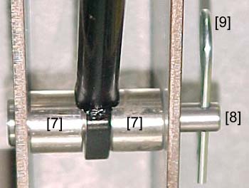
- Connect the narrow side of each piston to the brackets on the mainframe:
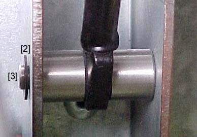
- Insert a spacer (252-00794A) inside the bracket next to the holes
on each side, as shown below [7].
- Insert a pin (290A2S226) through the spacers and the hole in the
narrow side of the piston, as shown below [8].
- Secure the pin with a hitch pin (385U51110), as shown below [9].
Note: Do not push the hitch pin all the way through.
- Connect the main power supply.
- Turn on the platesetter and start Controller.
- Turn on the air pressure.
- Close any open doors.
Logistics
| CSC |
Qty |
| CAM |
10 |
| CEU |
10 |
| CAP |
5 |
| CJP |
5 |
| CMA |
5 |
|
Material Disposition
|
|
Dispose of any components that you removed and did not reinstall.
|
| |
Technical contact
|
|
|
Date submitted
|
|
09 Apr 2003 |