Procedure
|
|
This procedure includes the following steps:
Determining configuration
The UDRC is available in several different hardware and filter configurations
to suit various type of thermal plates. There are two configurations planned:
- UDRC-BP
- Plate type—thermal, particulate debris-producing
only, such as KPG TP830A and Agfa P970
- Upgrade—backward-compatible replacement for
Morgan cabinet, upgradeable to LC configuration in factory or field
- UDRC-LC
- Plate type—process-less, producing particulate
debris and chemical emissions, such as Presstek Anthem
- Features—ensures that debris is properly collected
and that filter life is not exceeded, has specially designed filters
for specific plate emissions
- Ordering/shipping—part of Chemistry Free option
on Trendsetter® 800, 800Q, 400Q, Autoloader, and Spectrum
Pre-installation site inspection
Before installing the UDRC, verify that all site preparations have been
properly completed according to the following specifications:
- Universal Debris Removal Cabinet (UDRC) Site Preparation Guide
- Compressed air supply specifications
- Pressure: 8 bars (~120 psi)
- Capacity: 10 CFM (minimum)
- Humidity: dew point of 3°C (37°F)
- Particles: 1 micron, 1mg/m3 (maximum)
- Oil: 0.01 mg/m3 (maximum)
- Correct nozzle type is ordered, per
lens type
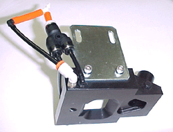
Check the type of lens installed on the machine. The following picture
shows the differences between the three possible lens types:

- Long Rodenstock or Zeiss—install the ablation nozzle
type II assy (500-00947B).

Note: Since the Long Rodenstock lens is
narrower than the Zeiss, an adaptor is provided, shown below, to bridge
the gap between the lens cover and the sides of the nozzle.

- Short Rodenstock—install the nozzle assy for lens 20 mm for
L400 (500-00064A).
Notes:
- A qualified electrician must complete all electrical work.
- You may need to order additional parts.
Preparing the machine for installation
- From the Lotem Controller application, move the carriage to the center
position, and then open the rear door.
- Close Lotem Controller, and then turn off the platesetter.
- In the distribution box, close the circuit breaker.
- Unplug the main power cable from the main power supply.
- Manually open the right door.
- Remove the rear trapezoid panel, and the rear panel.
- On the wall air pressure unit, close the air pressure valve to disconnect
the air supply to the platesetter.
- From the rear of the machine, disconnect the three unloading tray
molex connectors (two on the left side of the machine, and one on the
right).
- Disconnect the two unloading system air tubes.
- Remove the four unloading tray screws, and then remove the unloading
tray from the machine.
Installing the debris collection
nozzle
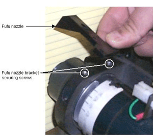
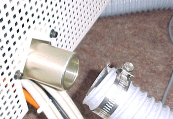
- From the rear of the machine, remove the two fufu nozzle bracket screws
(shown below), and remove the bracket from the optic head.
Note: Leave the fufu tube in place.
- Select the relevant nozzle according to the type of lens on the optic
head, as described in the Pre-installation site inspection
section.
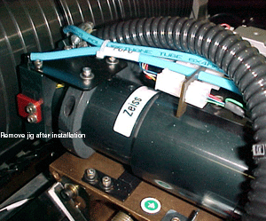
- Install the nozzle on the end of the optic lens, as described following.
Important: The purpose of the jig
on the nozzle type II is to ensure that the surfaces of the nozzle
and the lens will be on the same plane, to prevent the tail gripper
from hitting the lens or the nozzle. After you install the nozzle, remove
the jig.
- If you have the Long Rodenstock lens, install the adaptor
ring in the inside of nozzle type II, and secure it with two
screws.
- From above, place the nozzle over the lens, and press the nozzle
toward the optic head until it is flush with the lens protector.
- Secure the nozzle in place by tightening the two nozzle securing
screws on top of the nozzle.
- Insert the two supplied 8-32 x 3/8 inch screws, flat washers,
and spring washers into the additional nozzle securing holes and
tighten them to secure the nozzle bracket to the optic head.
Note: Be sure to apply Loctite 242 to each screw.
- If you installed Nozzle type II, remove the jig.
Connecting the vacuum hose
- Connect the short piece of 3/4" vacuum hose (344F10115) to the
nozzle and secure with a tie wrap.
- Thread the short piece of 3/4" vacuum hose from the left side
and under the bottom of the optical head.
Note: You may need to disconnect the earth connection
to enable the vacuum hose to pass under the optical head, and then reconnect
the earth connection.
- Connect the other side of the 3/4" vacuum hose to the adaptor
75"-1.25" (252-00431A), and secure with a clamp.
- Connect the adaptor 75"-1.25" to the polyure flex hose (344F10065),
and then secure it with a clamp.
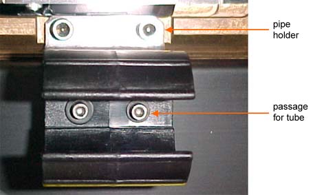
- Connect the pipe holder (252-00432A) to the carriage with two screws
(10-24*1/2"), flat washers, and spring washers, as shown below.
Note:
Since the two pipe holder screws also secure the shipping bracket, make
sure to remove the shipping bracket before reinstalling the pipe holder.
- Connect the passage for tube (290F9B892) to the pipe holder with two
screws (6-32*3/8"), flat washers, and spring washers, and then
route the vacuum hose through the passage for tube.

- Attach the fufu tube to the nipple on the right side of the nozzle.
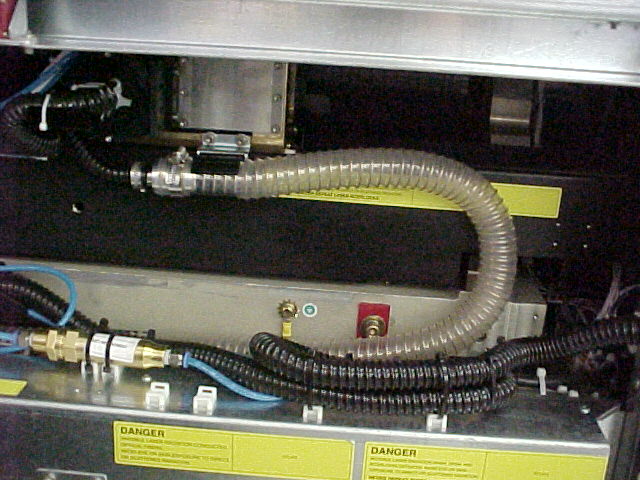
- Place the blue vacuum sensing tube inside the chain, and then secure
the last cover link of the chain with a tie wrap.
Note: The components in the cable chain should lie
flat, and untangled.
- Check if the UDRC supports a vacuum sensing option (LC).
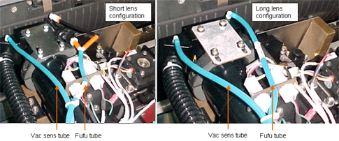
- Vacuum sensing option supported—remove the left fitting air
plug, attach the elbow (344A06040), and then attach the blue vacuum
sensing tube (that you added to the chain) to the elbow (shown below).
- Vacuum sensing option not supported—do not connect the tube
to the nozzle (as shown in step 3).
Note: Use a tie wrap to secure the tube so that
it is not loose.
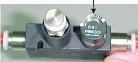
- Cut the fufu tube, and connect both ends to the air pressure regulator
(shown below).
Note: If the vacuum sensing tube is too long, cut it,
as required.

- Important: Manually rotate the
drum, and make sure there is sufficient clearance between the tail grippers
and the nozzle.
Preparing the light detector
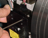
- Remove the light detector hood (cover) from the light detector (shown
below).
Note: Do not touch the light detector lens.
- Clean the light detector lens, using one of the following, soaked
with alcohol:
- Rice paper
- Special lens-cleaning paper
- cotton swab
- Clean the light detector lens again, using a clean piece of paper
or cotton swab (as described in the previous step) soaked with acetone.
- Remove the lens brush from the light detector hood, and then reinstall
the light detector hood.
Routing hoses, cables, and pipes
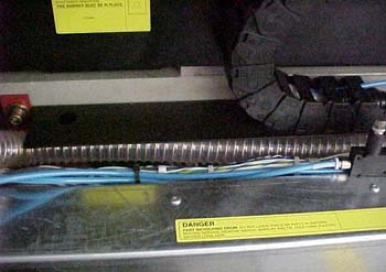
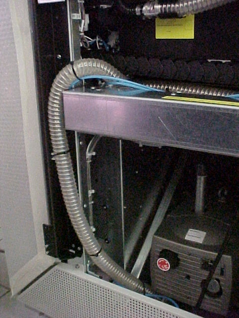
- Route the polyure flex hose underneath the chainholder, and then toward
the left and down the mainframe, as shown below.
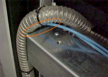
- Add the protective plastic to prevent damage to the polyure flex hose,
as shown below.
- Route the vacuum sensor tube toward the hole on the floor of the mainframe.
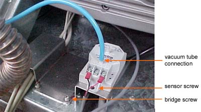
- Install the double bridge (252-00426A) on the mainframe with three
screws (10-32*3/8"), flat washers, and spring washers, as shown
below.
Note: Make sure that all the cables are routed through
the two bridges, as shown below, before tightening the screws.
Installing the vacuum sensor
- Install the vacuum sensor unit on the right side of the bridge with
two screws (6-32*3/8"), flat washers, and spring washers, as shown
above.
- If the UDRC supports a vacuum sensing option, connect the vacuum sensor
tube to the nipple on the vacuum sensor unit marked low,
as shown above.
- Connect the long piece of the 1-1/2" vacuum hose to the host
adaptor.
Note: Route the control cable alongside the braid.
Connecting the UDRC
- Perform the electrical connections between the Lotem 400 and the UDRC.
- UDRC BP
Local 2 cable—connect this control cable (220-00008A)
from the two-pin J5 Molex connector on the distribution box to the
UDRC connector. (The sensor is labeled J5 SOLENOID).
Note: The Local 2 control cable is good for machines with either
Local 2 or Local 3 boards.
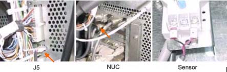
- UDRC LC
UDRC L cable—connect this control cable (220-00043A) as follows:
- NUC—connect the control cable from the NUC board (COM
6) to the UDRC J1 connector.
- Vacuum sensor—connect the vacuum sensor cable from
the vacuum sensor unit to the UDRC J1 connector.
- DIS J5—connect the DIS J5 cable from the J5 Molex
connector on the distribution box to the UDRC J5 connector.

- Position the UDRC as close to the rear of the machine as possible.
- Attach the vacuum hose to the hose adaptor (290B7B245) with a clamp.
- Connect the host adaptor to the trapeze (shown below) with two screws
( 8-32*1/2"), flat washers and spring washers.
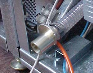
- Attach the trapeze to the mainframe with two screws.
- Attach the 1-1/2" vacuum hose from the adaptor to the back of
the UDRC.
- Reconnect the main power supply to the Lotem 400.
- Open the circuit breaker in the distribution box.
- Open the air supply valve on the wall air supply unit.
Note: Verify that the air pressure level is at least 6 bar.
- Start the PC controller.
- In the PC controller, set the values for the parameters according
to the type of machine (BP/LC). For more information, see
Testing functionality
- Insert cheaters into interlocks, as required.
- From the PC controller, activate the valve that supplies air to the
debris collection nozzle.
Under Utilities>Hardware>Expose
System> Laser System>Fufu Air Valve, click Start.
- Verify that the air pressure regulator on the nozzle is set to 40–45
psi.
- From the PC controller, activate the UDRC vacuum system, and verify
that suction occurs at the debris collection nozzle.
- Feel for leaks at all vacuum hose unions.
- From the PC controller, move the carriage to HP.
Watch the nozzle as the optic head passes the light detector. Verify
that there is adequate clearance and that they do not collide.
- Adjust the focus mechanical stopper by sending the motor to position
400, attaching the stopper to the optic tube, and tightening the screws.
- From the PC controller, move the carriage from HP
to EP. Watch the optic head as it moves. Verify that
there is adequate clearance between the optic head and the unloading
tray, and that the vacuum hose does not come into contact with the tray
at any point.
- From the PC controller, move the carriage to
the middle of the drum. Then, manually rotate the drum and verify that
the spoilers do not touch the nozzle.
Note: It is extremely important that the head
gripper and tail gripper spoilers do not come into contact with the
nozzle.
- Load a 0.3 mm plate and repeat step 9.
Note: Do not remove the plate.
- Remove all cheaters.
- Install the unloading tray, making sure to apply Loctite to each screw.
Note: Be sure to reconnect the three unloading tray
Molex connectors and the two air tubes.
- Install all panels, and close all doors.
IMPORTANT! Do not proceed
until all panels are properly replaced and all doors are closed.
- From the PC controller, rotate the drum at a rate of 900 RPM.
IMPORTANT! Be prepared to stop
the machine immediately either from the PC controller or using the main
circuit breaker.
- While the drum is rotating, move the carriage from HP
to EP. While the carriage is moving, listen carefully
for any sounds that may indicate malfunction, such as the nozzle colliding
with something. If you hear anything of this sort:
- Stop the machine immediately.
- Open the rear door and check the clearance between the debris
collection nozzle and other machine parts.
|

