Home | Contact Us | Submit Troubleshooting Info | Search | Help


    Output | Software Solutions | Proofing | Color, Screening and Calibration | Scanning | Digital Photography | Consumables | POS


Adjusting Plate Attachment Pins for Lotem 400


Product


Lotem® 400


Background

  The image exposed on a plate must be parallel to the edge of the plate. If the plate attachment pins are not parallel, they cause the plate to skew, resulting in an image that is not parallel to the edge of the plate.
This procedure describes how to adjust the plate attachment pins to ensure that the plate is parallel to the pins.

Requirements

 
  • Drum pin registration fix assembly jig, part number 291A9B155
  • Drum pin adjustment holder (long), part number 252-04921A
  • Microns dial indicator

Procedure

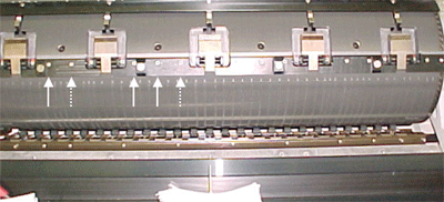
  Note: Make the measurements and adjustments to either the two inner pins or the two outer pins. The inner pins are higher than the two outer pins.
Measuring Parallelism
  1. Expose a strip along the drum, at a distance of 20 mm from the edge of the plate.
  2. Process the plate.
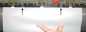
  3. Measure the distance between the edge of the image and the edge of the plate where the pins touch the plate, as shown. If the difference between the two measurements is greater than ±20 microns, perform the adjustment procedure.
Adjustment Procedure

Select one pin to be the reference, and make the adjustment, described below, to the other pin.

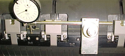
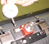
  1. Attach the drum pin registration fix assembly jig.
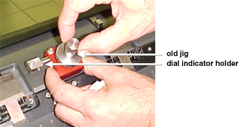
    • For Lotem 400 non-small device—example shown with old jig and drum pin adjustment holder (short)
    • For Lotem 400 small devices, do one of the following:
      • Order the new jig and drum pin adjustment holder (long).
      • Use the old jig with the new drum pin adjustment holder (long).
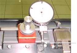
  2. Make sure that the dial indicator holder is on the left if you adjust the left pin, and on the right if you adjust the right pin. To move the dial indicator holder to the other side, release the two screws on the jig, remove the dial indicator holder and insert it from the other direction, and then tighten the two screws.
  3. Insert the dial indicator.

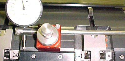
    Make sure the dial indicator arm touches the spoiler.
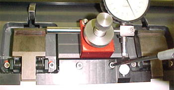
  4. Loosen the screw(s) closest to the Spoiler, as shown.
    • Inner Spoilers have three screws. Loosen the two closest to the Spoiler.
    • Outer Spoilers have two screws. Loosen the one closest to the Spoiler.
  5. Tap the Spoiler gently to move it the difference between the two measurements obtained in step 3 of the Measuring Paraellelism section.
    For example, if the left measurement was 60 microns less than the right measurement, tap the left spoiler gently until the Dial Indicator shows that it has increased by 60 microns.
  6. Tighten the Spoiler screws.


Technical contact(s)
 

Content owner: Mario Amir
See the Escalation page for escalation contacts.

Date submitted
 

04 Feb 2002


    Copyright © 2005 Creo Inc. All rights reserved. Confidential. Back to top.