
To obtain good registration (in the high axis) all loaded plates
should touch the two pins in the head gripper spoilers.
The sequence for loading a plate to the drum is performed in two
steps:
Moving the plate forward until it almost touches the pins in head gripper
spoilers.
Pressing the plate against the pins in the spoilers.
First step
At the first step the drum moves to a loading position
(Parameter name - Load Head Gripper Location ~(-204)).
The actuators open the Head grippers.
The Loading stopper door opens.
The Loading motor moves the plate forward 3 mm away from the
pins
(Parameter name - Load Plate to Drum Position ~104).
Second step (Extra)
The Loading Motor moves the plate forward (with a deferent
torque for each plate thickness). After 1.6 seconds, the head grippers are
released and the plate is grasped by the head grippers. During the 1.6 seconds,
the plate should reach the two pins and press against them, but without making
any marks on the plate edges.
Parameters being used in the Procedure
Parameter Name
Default
Remark
Load Head Gripper Location
-204
Location of drum
Load Plate to Drum Position
104
Adjusted by this procedure
Loading Motor Moment For 0.15 Seq
15
The moment used in second step
Loading Motor Moment For 0.2 Seq
30
The moment used in second step
Loading Motor Moment For 0.3 Seq
80
The moment used in second step
Load Plate to Drum Speed
4
Loading motor speed in first step
Load Plate Extra to drum Speed
0.4
Loading motor speed in second step
Load Plate Extra to Drum (mm)
80
Before performing any of the calibration procedures, the
following actions should be taken:
Open the Password for Service Engineer as follows:
Open the Utilities window and click the Users.
In the Users window, open the User Type menu. Select Service Engineer,
and in the Password field, enter AAA.
Select Hardware in the Utilities menu. In the Hardware
window, open the Loading System menu, and below it Loading System
is displayed again. Double click Loading System and the large Loading
System window appears.
In this window click on Init Drum (1), and wait for the action to
be completed.
Prior to the procedure:
It is recommended to perform this procedure after adjusting the pressure
of the loading motor on the thinnest plate (0.15 mm plate is preferable).
Procedure
Note: This can only be performed after performing the gripper
calibration procedure.
Open the Drum System menu and click on the Drum Motor.
The Drum Motor window appears.
Open the Gripper System and click on the Load Gripper Valve.
The Load Gripper Valve window appears.
Open the Loading System menu > Loading Plate To Drum. Click on the Solenoids
Valve menu > Loading Stopper Valve.
The Loading Stopper Valve window appears.
Open the Drum System > Gripper System > Load Gripper. Click on the
Load Gripper Valve. The Load Gripper Valve window appears.
In the Hardware window, click on Others. Below it, Lotem 400
appears. Select this item and click the right-hand mouse button.
Double click on IO Objects > Loading System, and then Setup in this
window.
Record the value of the Load Head Gripper Location (~-204).
Close all windows opened in this step.
Open the front door and insert a motor cheater.
Place a plate of 0.3 mm thickness on the loading tray and push it forward
until it is stopped by the Loading Stopper.
Mark with a pen on the plate a line, parallel to the loading driver.
Move the drum to the position which you recorded on step 5.B (~-204) with
speed of 100 RPM.
Switch on the Load Gripper Valve.
Switch on the Loading Stopper Valve.
Note: The Loading Stopper Valve has a time limit of 3 minutes.
Press the plate forward until it reaches the pins in the Head grippers.
With a pen, mark a second line on the plate, parallel to the loading driver.
Pull out the plate and measure the distance between the two lines.
Note: At this position you can also check that the Plate Driving Unit is
parallel to the Drum.
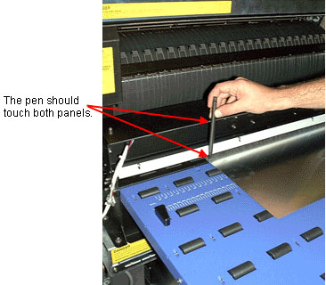
Close the Loading Stopper Valve.
Close the Load Gripper Valve.
In the Hardware window, click on Others. Below it, Lotem 400 appears. Select
this item and click the right mouse button.
Double click IO Objects > Loading System, and then Load Plate in this
window.
Copy the value you received in the previous step to Load Plate to Drum
Position subtracting 3.
Test
Load a new plate and expose a Uni file or Grid.
Check and measure that the top edge of the file is parallel to the edge of
the plate.
Place a plate on the loading tray but with a small angle in reference to
the drum.
Check that during the second stage of the motor moves the plate parallel to
the drum and touches both pins.
Load the thinnest plate (0.15 mm plate is preferable) and check that the
loading motor does not damage the plate. If you see marks on the center of
the plate than you need to adjust the pressure of the loading motor.
Troubleshooting
Symptom: Skew of 0.5 mm and higher.
The fault: The Head Gripper is closes before the plate
reached the pins in the Head gripper spoilers.
Solution: Increase the first step by changing the
parameter Load Plate to Drum Position.
Test: Load a plate and mark with a pen the location of
the pins.
Unload the plate and check the edge of the plate (near the marks) for small
marks made by the pins.
Symptom: Skew of 0.1 to 0.2 mm
The fault: The plate is crushed by the pins.
Solution:
Decrease the moment for the relevant plate thickness.
Verify that 0.12 pins are installed.
Check the pressure of the loading motor.
Check parallelism of Loading System to the optomech.