Procedure
|
|
Removing the paper disposal roller
- Shut down Lotem Controller and turn off the platesetter.
- Disconnect the main power supply.
- Remove the interlock covers on both sides of the MCU.
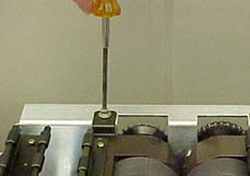
- On the right side of the machine, remove the three hex screws from
the shield of the disposal roller that is closest to the drum.
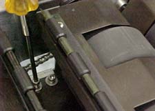
- Loosen the screw that holds the gear wheel, but do not remove the
gear wheel.
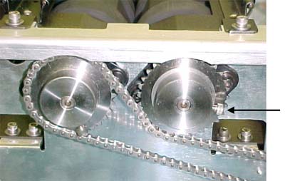
- Loosen the chain.
- Loosen the screw on the motor gear wheel, and then remove the motor
gear wheel.
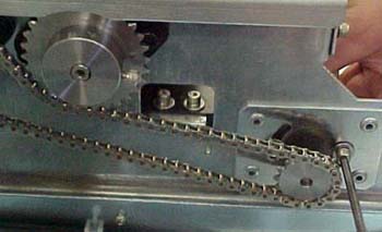
- Remove the gear wheel.
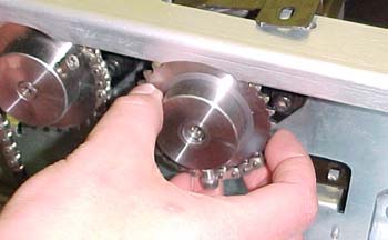
- Remove the two hex screws that hold the disposal roller bearing.
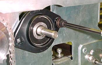
- Loosen, but do not remove, the two set screws on the disposal roller
shaft.
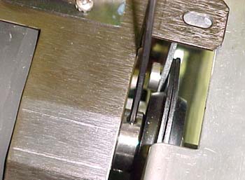
- Remove the bearing and the bearing housing.
- On the left side of the machine, repeat steps 4-11.
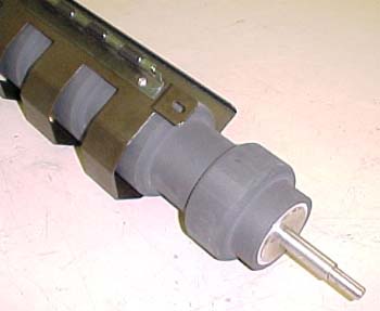
- Lift the disposal roller assembly out of the machine.
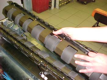
- Slide the roller assembly out of the shield.
Installing the paper disposal roller
Note: Make sure to use Loctite® 242 on all screws
except the set screws.
- Slide the disposal roller assy into the paper run out shield.
Note: Perform steps 2-6 on the right side of the machine.
- Insert the disposal roller assembly into the machine.
- Insert the bearing and the bearing housing, and then insert (but do
not tighten) the two hex screws that hold the bearing housing. (See
step 9, above.)
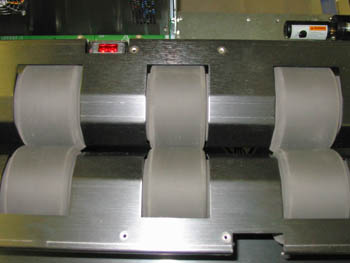
- To position the roller correctly, make sure that it is exactly aligned
with the other roller.
Note: Make sure to use Loctite 638 on the four set screws.
- Tighten the set screw on the flat side of the shaft.
- Tighten the two hex screws that hold the bearing housing.
- On the left side of the machine, repeat steps 3, 5, and 6.
Note: There is no need to adjust the roller pressure
again.
- On each side of the machine, tighten the set screw on the round sides
of the shaft.
- On each side of the machine, insert and tighten the three hex screws
that secure the paper run out shield, as shown in step 4 of the previous
section.
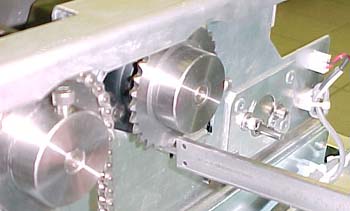
- Install the large gear wheel and slightly tighten the two screws.
- To adjust the gear wheel, use a caliber to measure a distance of 23
mm from the base of the frame to the edge of the gear wheel, and then
adjust the gear wheel position and tighten the screws.
- Install the motor gear wheel and slightly tighten the two screws.
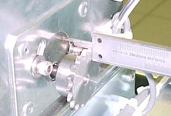
- To adjust the motor gear wheel, use a caliber to measure a distance
of 20.5 mm from the base of the motor to the edge of the motor gear
wheel, and then adjust the motor gear wheel position and tighten the
screws.
- To adjust the chain, loosen the two screws that secure the motor,
loop the chain around the two gear wheels, and then tighten the two
motor screws.
Note: The chain should not be too tight or too loose.
|

