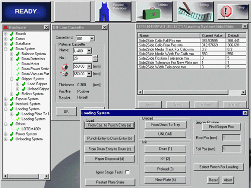
Before performing any of the calibration procedures, the following actions should be
taken:
Open the Password for Service Engineer as follows:
Open the Utilities window and select the Users window.
Open the Define User window from this window, in the User Type menu. Select Service
Engineer, and in the Password field, enter AAA.
Open Hardware in the Utilities window. In the Hardware window, open the menu Loading
System, and underneath it Loading System will be displayed again. Double click this line,
and the large Loading System will appear.
In this window click on Init Drum (1), and wait for the action to be completed.
Prior to the procedure:
Ensure the performance of the Init Drum function through Loading System.
Ensure that motor interlocks are disconnected. Drag the tail gripper to
the end of the track (close to the head gripper). Connect motor interlock.
Check that the machine is updated to plate size 550 (around the drum) X
650 (along the drum) by clicking on the window Routine Function and opening
the window Off Line Plates. Note: You do not need to load a plate, only to define the plate in
the Controller software.
Procedure
Note: This procedure can only be performed after the Gripper Calibration Procedure and
the Balance Calibration Procedure has been performed.
Perform Preload by Clicking on the Preload line (3) (in the Loading System window). The
machine will adjust the tail gripper to the correct location according to the definition
of plate length.
In the Hardware window, click on the line Others, and underneath it, select the line
Lotem 400, and click the right-hand mouse button.
Double click on IO Objects, and in the window that opens, double click on Loading
System.
Double click on Side 2 Side, and in the resulting window change the value in the line
Side 2 Side Wide Tolerance to 50.
Perform Save & Send.
In the Loading System window:
Click on the line Find Gripper Pos. and wait for this operation to be completed.
Write down on a piece of paper the results in Rise Pos (mm) and in Fall Pos (mm).
Perform this action three times, and calculate the average vale for Rise and for Fall.
In the Side 2 Side window opened in section2.2nd, update the values of the lines Side 2
Side Calib Fall Pos (mm) and Side 2 Side Calib Rise Pos (mm), respectively.
Return the value of the line Side 2 Side Width Tolerance to the default value opened in
section 2.2nd, and perform Save & Send. Close all the windows opened in section 2.
Note: Calibration can be performed with a plate length other than 550 if the plate
length defined in the window Side 2 Side Media Width for Calib (mm) is changed. This line
can be reached by using the instructions in section 2, in the last window.
Calibration check:
Enter a plate size other than that defined in the machine at present, in the Loading
System window,
Click on line New Plate (4). The machine will calibrate the grippers and weights.
After completing the operation click on New Plate (4) again.
The machine should only
perform a scan to check the location of the grippers and weights.
Note: If the machine performs another drag of the grippers, there is a problem with the
calibration.
Perform New Plate (4) several times for the same plate size definition to ensure that
the grippers are not dragged.
Perform sections 1 to 4 for several plate sizes.
Open Parameter windows in Side to Side System Procedure.