Home | Contact Us | Submit Troubleshooting Info | Search | Help
Output | Software Solutions | Proofing | Color, Screening and Calibration | Scanning | Digital Photography | Consumables | POS
Home | Contact Us | Submit Troubleshooting Info | Search | Help
Output | Software Solutions | Proofing | Color, Screening and Calibration | Scanning | Digital Photography | Consumables | POS
Isolating the internal wires of drum encoder connector
Prevent possible lose of drum speed control due to short
circuit of wires.
Isolating inner
wires inside connector to MCF board.
Open side door, shut machine main power off and disconnect encoder Connector from MCF board.
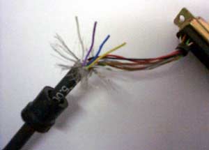
Open connector, remove copper tape and slip rubber fitting down along Cable [Pic. # 2721]
Expose 2 cm of inner wires by carefully removing outer (black) isolation.
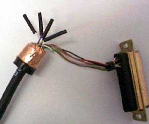
Peel down shielding wires and free all cut wires. Insert a 1.5cm piece of shrinking isolation on all cut wires and heat to shrink, or apply isolating tape).[Pic. # 2722]
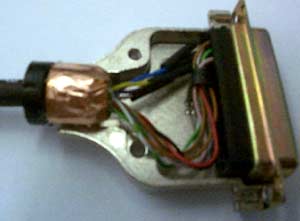
Wrap shielding wires around rubber fitting and apply copper tape. (This is important for good grounding of the encoder ) [Pic. # 2723].
Fit all wires back into the connector and close with cover.
FCO Kit Contains:
401A00200x15cm (copper tape)
405A01004x10cm (shrinking isolation)
(FCO Document)
Photographs
N/A
CSA-30; CSE-30; CSAP-10; CSN-10;CSMA-10