Field Change Order #25223 - Large Suction Cup Replacement in Loading System
S. Avisror
January 26, 1999 revised November 2001 by Dennis Kaliser
Machine S/N:
all machines under 99021761
Type of Change:
Conditional
Reason for change
Replace the Loading System suction cups of with bigger cups for better suction
to plates. Newer cups improve plate transfer from short pins to the drum. There
is independent control of the three center suction cups.
Description of change
Replace the suction cups and nipples. Add a new vacuum valve and arrange the
suction cups so that they can be controlled by the three vacuum valves.
Tools
Phillips #2 screwdriver
7mm and 16mm open end wrenches
Locktite 242
Change Procedure
Open the front cover.
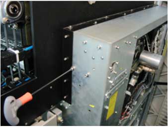
Using a Phillips screwdriver, open the three Phillips screws in front of
the X-Y bar cover.
Lift the cover of the X-Y bar.
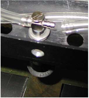
Disconnect the air tube
from the rod of the suction cup.
Undo the screw on top of the nipple.
Keep the washer.
The nipple is connected
to the top of the rod.
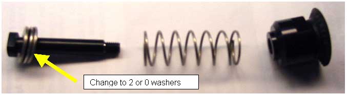
The number of washers
varies for each suction cup.
Insert the correct number of washers
according to the following chart.
Cup #
1
2
3
4
5
6
7
# Washers
2
2
0
0
0
2
2
Note: Follow step 5 Splitting Vacuum Nipples in the Loading System to see
what type of nipple you need to install.
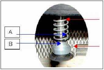
Using two wrenches, 16 mm and 7 mm, release the suction cup (A - as shown
below) from the rod (B - as shown below).
Hold the spring and remove the rod from the X - Y bar.
Connect the new rod to the nipple (on the top) with the screw.
Don't forget the washer.
Apply Loctite 242 to the thread on the suction rod.
Screw the suction cup to the rod.
Slide the spring over the rod.
Connect the rod (on the bottom) with the suction cup to the nipple and
tighten the screw.
Repeat the same steps for all 7 of the suction cups.
Addition of a Vacuum Valve in a Loading Manifold
Required Tools
A short, small flat screwdriver
Allen key #10
9/16" or 14 mm wrench
½" or 12 mm wrench
Required Parts
Blue vacuum pipe
344F10131 (3 Meter )
Vacuum valve
47M72200 x 1
90° connector
344C71000 x 1
Vacuum valve cable
504L2D180
Installation Procedure
Dismantle the loading
vacuum manifold unit
from the machine frame.
The unit is held to the
frame by two 9/64" screws.
Remove the manifold
from the frame to gain
easy access to the electrical
and pneumatic connections.
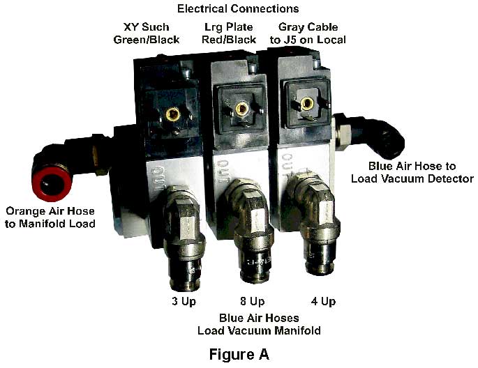
Disconnect the three electrical connectors attached to the load vacuum manifold.
See Figure A
Disconnect the orange vacuum hose leading to the manifold load.
Disconnect the three blue vacuum hoses leading to the loading vacuum manifold.
Disconnect the blue vacuum hose leading to the load vacuum detector.
Dismantle the square plugs from the manifold unit.
Attention: Keep the gaskets installed underneath the dismantled plug.
Install the 344C71000 connectors onto the 347M2200 vacuum valves
Install the valve on the vacuum manifold unit from the removed plug.
Attention: Insert the gaskets between the valve and the manifold.
Re-connect the orange vacuum hose back in place.
Re-connect the three electrical connectors to the same positions that they
were previously connected to.
Re-connect the blue vacuum hose joining the manifold unit and the Load
vacuum detector.
Connect the three blue vacuum hoses back in their place.
Re-install the vacuum manifold unit back to its place on the frame.
Note: For training purposes only, when simply removing and replacing
the same manifold, only follow steps 1 through 7 and 10 through 14.
Connect a new blue 344F10131 vacuum pipe to the new valve.
Insert the new blue vacuum pipe that was installed with the vacuum manifold,
through the chains into the loading system.
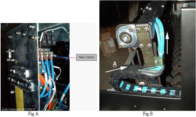
Follow the arrows in figure B to see how to add the Blue tube for the three
suction cups inside the chain of the X - Y vacuum system.
Note that the arrow with the letter A indicates that you need to open the
chain cover in order to insert the tube to the chain. See Figure B.
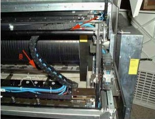
Follow the arrows in figure C to see how to insert the vacuum tube to the
rest of the chain. The arrow C indicates that you need to open the cover of
the chain in order to insert the tube to the chain.
Connection of the valve cable to the right Local - Dismantle the cable
J5 that is connected to the right Local Box, insert the to pins (red and black
pins) inside the isolation of the cable J5. Connect the red pin to pin 8 in
the connect and the black pin to pin 9 in the connector
Registry Update - In order to activate the valve , go to the registry/
Lotem 800V / I/O object / small plate / suction valve/ Change the open status
from 0 to 1
Restart the Lotem application
Splitting Vacuum Nipples in the Loading System
Required Tools
Phillips screwdriver
Wire Cutter
Open wrenches 9/32"; 5/16"
A small flat screwdriver
Required Parts
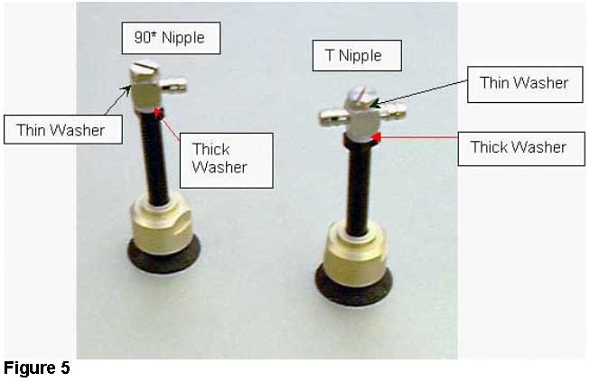
90° Nipples
344C70010 x 5 (2 spare)
See figure 5
Y (T) Nipples
344C70020 x 5 (1 spare)
see figure 5
10 cable clips
203A10030
Blue pipe for the 4 up Plate
344F10131
length 0.7 Meter
Blue pipe for the 8 up Plate
344F10131
length 0.9 Meter
TYGON flexible tube
344F10036
0.35 Meter (Tube for the 3 Central suction cups)
Installation Procedure
Disconnect the vacuum tubing system from the 5 central nipples in the vacuum
system.
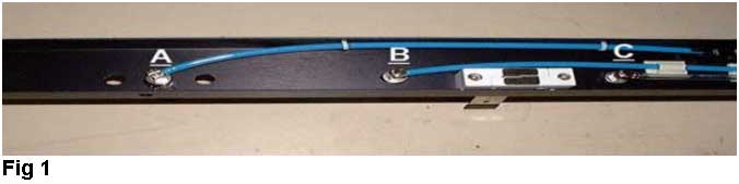
Replace the existing Nipples (See figure1 nipples A, B, C) with 90°
344C70010 Nipples. See figure 5.
Note: In order to tighten the nipple to the suction cup rod, hold the flat
screw of the nipple to the flat screwdriver and tighten the nipple with a
wrench. (1/4 of turn).
The nipple may break if you over tighten the screw of the nipple.
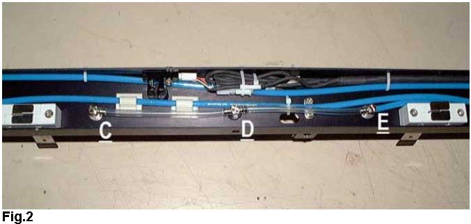
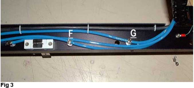
The nipples D, E, F, G of the x - y system should be the Y type nipple
344C70020. See figures 2 and 3 and 5.
Insert the new blue vacuum pipe that was installed with the vacuum manifold,
through the chains into the loading system. See step 4, O
Connect 80cm blue vacuum pipe to nipples A - G nipple. This is the 8 up
suction cups. See figure 1 nipple A and figure 3 nipple G.
Connect a 52.5 cm blue vacuum pipe between nipples B - F. This is the 4
up suction system. See figure1 nipple B and figure 3 nipple F
Connect a 13-cm blue vacuum pipe between nipple C and D. See figure 2
Connect a 12.5 cm blue vacuum pipe between nipples D and E. Nipple D and
E should be the Y 344C70020 Nipple type. See figure 2 nipples D and E.
Connect the new vacuum pipe coming from the vacuum manifold of the loading
system to Nipple E. See figure 2 nipple E.
Route all pipes and electric wiring within the vacuum system assembly and
tie them using the 203A10030 cable clips.
Attention: Transfer the excess cable and piping system towards the chain on
the right-hand side of the system.
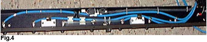
Follow figure 4 to see the arrangements of the vacuum tubes inside the
x-y vacuum system.
Close the vacuum assembly cover of the loading system.
Check that all the vacuum nipples move freely and are not distorted in
their movement.
Test Procedure
Load a plate when the front door is open and check the attachment of the
suction cups to the plate. Load one plate in the loading cassette and perform
a loading sequence. See that the x-y system grabs the plate with out any problem.
Check the loading system with all plate sizes the customer uses.
As soon as you implement this FCO, inform the customer that he can load
up to 100 plates.
Check the attachment of the plate to the pins on the drum.
Expose 4 plates CMYK and check their registration.