Field Change Order #27501 - Unload Force Improvement on GTO Unloading Tray
Description
Improving the unload force between the unload rollers, only on GTO's unloading
tray.
Prepared By: Itai Peperovich
FCO Kit No.: 510F27501
Comp. Level:
Machine S/N:
Catalog No. 507F2D658A
S/W Affected:
Type of Change:
Conditional
Total Number of Pages:5
Product Mgr: Nir Halup
Approval Date:
Product Support:
Itai Peperovich
Approval Date: 19-04-2001
Customer Support Mgr: Kuty Paperny
Approval Date:
Reason For Change
To Improve the rollers reliability:
The edges of small plates going through the rollers were actually cutting
the rollers.
The damaged area on the roller, were making scratches on bigger plates going
through the rollers. Now the plate edges are not pressed between the two rollers.
To Improve the unload force:
By reducing the rollers diameter on the sides (2 mm on each roller), actually
increased the pulling force of the rollers by 10% - 30%, according to the
plate's size.
Description of Change
Replacing the damaged rollers with the new rollers.
Change Procedure
Open the rear door through the GUI.
Disconnect the unloading tray's connectors.
Remove the 10-32 NC screws securing the unloading tray to the machine.
Remove the tray and put it on a working table.
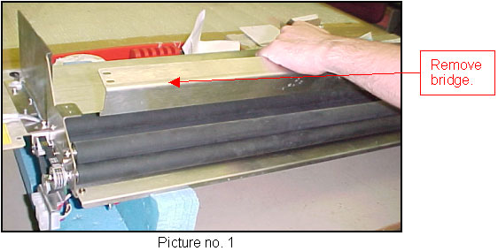
Remove the bridge by opening the 4 screws on the side (see picture no. 1)
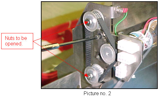
Release the belt's tension by releasing the two screws on the side, and
remove the belt (see picture no. 2).
Open the two nuts securing the two wheels with a 3/8" open wrench (see
picture no. 2).
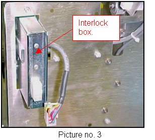
Disconnect the interlock box cable and remove the box from the unload tray
(see picture no. 3).
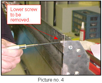
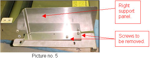
Open the 5 screws connecting the right support panel to the tray and remove
it (there is another screw in the bottom of the right support panel).
see pictures no. 4 & 5.
Remove the two belts wheels, in order to remove the lower one you need to
slightly lift the right side of the roller.
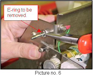
Remove the two R-rings from the lower rollers (see picture no.6).
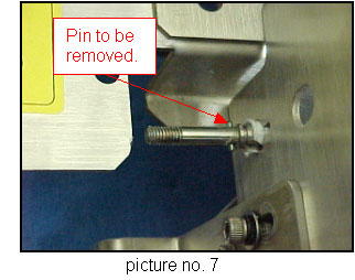
In order to remove the lower rollers you need to remove the pins inside
the rollers (see picture no. 7).
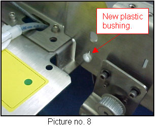
Put new plastic bushings inside the holes in the left and right support
panels (see picture no. 8).
Put the two new lower rollers in the left panel support.
Insert the two pins, use loctite 638, and place the pins in the middle
of the rollers shaft.
Place the belts wheels on both lower rollers.
Attach the wheels to the pin on the roller's shaft, and put loctite 242
on the roller threads.
Insert a spring L/W and flat washer and close the two wheels with a nut.
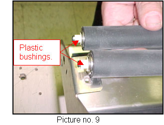
Replace the two upper rollers; don't forget to put the plastic bushings
(see picture no. 9).
Assemble the right support panel; make sure all 4 of the rollers edges
are inside the panel before closing the screws, use loctite 242.
Push the right support panel to the left panel, in order to reduce the
rollers movement to the sides.
Tighten the screws on the right panel, and the one on the bottom also.
Put back the two E-rings on the rollers.
Put the belt back on the wheels, and push the motor bracket in order to
tighten the belt. Before tightening the two screws, make sure the motor is
in the middle of both wheels.
Reinstall the interlock box, and connector.
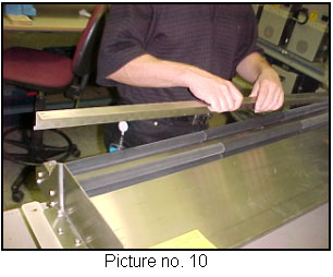
Reinstall the bridge, and close with 4 screws and loctite 242 (see picture
no. 10).
Test Procedure
Move the rollers with your hands, and make sure all rollers rotate freely.
Reinstall the unload tray on the machine, close all screws with loctite
242.
Reconnect all connector to the unload tray.
Put a cheater on the rear door interlock.
Open the unload motor in the GUI.
Activate the motor; make sure the rollers are turning easily and quietly.
Stop the motor.
Load a couple of plates from different sizes and thicknesses.