

Home | Contact Us | Submit Troubleshooting Info | Search | Help
Output | Software Solutions | Proofing | Color, Screening and Calibration | Scanning | Digital Photography | Consumables | POS
Home | Contact Us | Submit Troubleshooting Info | Search | Help
Output | Software Solutions | Proofing | Color, Screening and Calibration | Scanning | Digital Photography | Consumables | POS
| Prepared By: Itai Peperovich | FCO Kit No.: 510F27707;A;B;C |
| Comp. Level: | Machine S/N: |
| Catalog No. : | S/W Affected: |
| Type of Change: Mandatory | Total Number of Pages: 5 |
| Product Mgr: Stefan Kleinman | Approval Date: |
| Product Support: Itai Peperovich | Approval Date: 12-07-01 |
| Customer Support Mgr: Assaf Zach | Approval Date: |
Reason For Change
Description of Change
Change Procedure
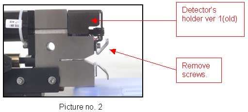
Note: The punch upper guide is part of the new holder; the lower guide must be attached with the double stick paper. If attached with screws, secure with Loctite 242.
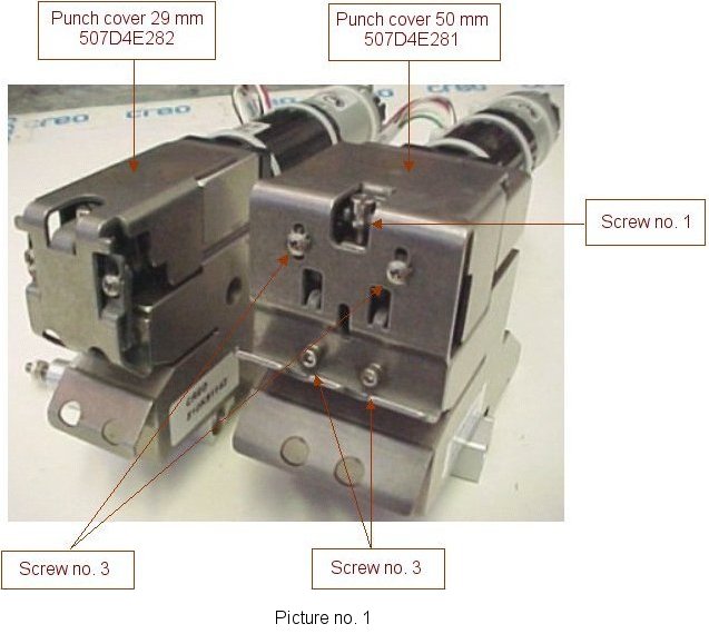
Picture no. 1
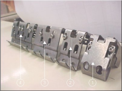
1 = Covers for spiral and single punches, 29 mm width.
2 = Covers for double punches, 29 mm width.
3 = Covers for double and triple punches, 50 mm width.
4 = Covers for double and triple punches, 69 mm width.
Parts List
|
PART |
QTY |
DESCRIPTION |
| 374A00080 |
1 |
Packing Label-Wht |
| 380A01020 |
4
|
Soc Hd Cap Stst 4-40*1/4" |
| 382A05000 |
4
|
Flat Washer Stst #4 |
| 382D04000 |
4
|
Spring L/W Stst #4 |
| 391I60617 |
1
|
Envelope 16x21 cm Air Bubbles |
| 507D4E282 |
2
|
Punch Detector Short Cover 29 mm Assembly |
| 291A6A991 |
2
|
Punch Guide-30+Glue |
| 719-27707 |
1 |
FCO Document |
|
PART |
QTY |
DESCRIPTION |
| 374A00080 |
1 |
Packing Label-Wht |
| 380A01020 |
4 |
Soc Hd Cap Stst 4-40*1/4" |
| 382A05000 |
4 |
Flat Washer Stst #4 |
| 382D04000 |
4 |
Spring L/W Stst #4 |
| 391I60617 |
1
|
Envelope 16x21 cm Air Bubbles |
| 507D4E281 |
2 |
Punch Detector Short Cover 50 mm Assembly |
| 291A6A992 |
2 |
Punch Guide-50 +Glue |
| 719-27707 |
1 |
FCO Document |
|
PART |
QTY |
DESCRIPTION |
| 374A00080 |
1
|
Packing Label-Wht |
| 380A01020 |
8
|
Soc Hd Cap Stst 4-40*1/4" |
| 382A05000 |
8
|
Flat Washer Stst #4 |
| 382D04000 |
8
|
Spring L/W Stst #4 |
| 391I60617 |
1
|
Envelope 16x21 cm Air Bubbles |
| 507D4E280 |
2
|
Punch Detector Short Cover 69 mm Assembly |
| 291A6A991 |
4
|
Punch Guide-30+Glue |
| 719-27707 |
1
|
FCO Document |
|
PART |
QTY |
DESCRIPTION |
| 374A00080 |
1
|
Packing Label-Wht |
| 380A01020 |
4
|
Soc Hd Cap Stst 4-40*1/4" |
| 382A05000 |
4
|
Flat Washer Stst #4 |
| 382D04000 |
4
|
Spring L/W Stst #4 |
| 391I60617 |
1
|
Envelope 16x21 cm Air Bubbles |
| 507D3E740 |
2
|
Single Punch Detector Adjustment Assembly |
| 291A6A991 |
2
|
Punch Guide-30+Glue |
| 719-27707 |
1
|
FCO Document |
Attached Documentation
None.
Material Disposition
Logistics
| CAM | : |
60
|
| CEU | : |
60
|
| CAP | : |
10
|
| CJP | : |
10
|
| CMA | : |
10
|
| Other | : |
|
| No Limit |
|
Schedule supplies for first lots for 510F27707:
|
DU |
|
Month |
QTY |
Month |
QTY |
Month
|
QTY
|
| CAM |
: |
July |
20 |
August |
20 |
September
|
20
|
| CEU |
: |
July |
20 |
August |
20 |
September
|
20
|
| CAP |
: |
July |
4 |
August |
3 |
September
|
3
|
| CJP |
: |
July |
3 |
August |
4 |
September
|
3
|
| CMA |
: |
July |
3 |
August |
3 |
September
|
4
|
|
Other |
: |
|
|
|
|
|
|
| CAM | : |
6
|
| CEU | : |
5
|
| : |
3
|
|
| CJP | : |
3
|
| CMA | : |
3
|
| Other | : |
|
| No Limit |
|
Schedule supplies for first lots for 510F27707A:
| DU |
|
Month
|
QTY
|
Month | QTY | Month | QTY |
| CAM | : |
July
|
6
|
|
|
|
|
| CEU | : |
July
|
5
|
|
|
|
|
| CAP | : |
July
|
3
|
|
|
|
|
| CJP | : |
July
|
3
|
|
|
|
|
| CMA | : |
July
|
3
|
|
|
|
|
| Other | : |
|
|
|
|
|
|
| CAM | : |
11
|
| CEU | : |
10
|
| CAP | : |
3
|
| CJP | : |
3
|
| CMA | : |
3
|
| Other | : |
|
| No Limit |
|
|
Schedule supplies for first lots 510F27707B/510F27707C:
| DU |
|
Month
|
QTY
|
Month |
QTY
|
Month
|
QTY
|
| CAM | : |
July
|
11
|
|
|
|
|
| CEU | : |
July
|
10
|
|
|
|
|
| CAP | : |
July
|
3
|
|
|
|
|
| CJP | : |
July
|
3
|
|
|
|
|
| CMA | : |
July
|
3
|
|
|
|
|
| Other | : |
|
|
|
|
|
|
719-27707 Rev C