Home | Contact Us | Submit Troubleshooting Info | Search | Help


    Output | Software Solutions | Proofing | Color, Screening and Calibration | Scanning | Digital Photography | Consumables | POS


Field Change Order #27835 - Unload Force Improvement on Regular Trays

Description: Improving the pulling force between the two unload rollers on the unloading tray.

Prepared By: Itai Peperovich

FCO Kit No: 510F27835

Comp. Level:

Machine S/N:

Catalog No: 507F1L203B

S/W Affected:

Type of Change: Conditional

Total Number of Pages: 5

Product Mgr: Nir Halup

Approval Date: 31-07-2001

Product Support: Itai Peperovich

Approval Date: 31-07-2001

Customer Support Mgr: Assaf Zach

Approval Date:

1. Reason For Change

  1. To improve the rollers reliability:
    The edges of small plates that pass though the rollers cut the rollers.
    The damaged area on the roller scratched the bigger plates when they passed through the rollers.
  2. To improve the unload force:
    By reducing the rollers diameter on each side (2 mm on each roller), the pulling force of the rollers is increased by 10% - 30%, according to the plate's size.

2. Description of Change

Replace the damaged rollers with the new rollers.

3. Change Procedure
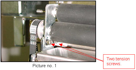
  1. Open the rear door via the GUI.
  2. Disconnect the unloading tray's connectors.
  3. Remove the 10-32 NC screws, which secure the unloading tray to the machine.
  4. Remove the tray and put it on a working table.
  5. Release the belt's tension by releasing the two screws on the side, and then remove the belt (see picture no. 1).

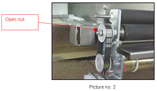
  1. Open the nut, securing the wheels with a 3/8" open wrench (see picture no. 2).

  1. Remove the sprocket from the roller shaft.
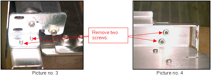
  2. Open the two screws, connecting the rollers support bracket (not the motor side) to the tray, and remove it. Access the screws from the backside of the tray (see picture no. 3 & 4).

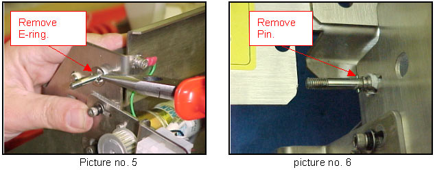
  1. Remove the E-ring from the lower roller (see picture no.5).

  1. In order to remove the lower roller, remove the pin inside the roller (see picture no. 6).
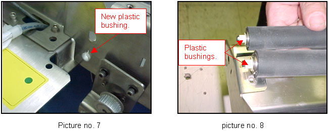
  2. Place new plastic bushings inside the holes, on the left and right support brackets (see picture no. 7).

  1. Place the two new rollers on the left panel support.
  2. Insert the pin, use loctite 638; place it in the middle of the roller shaft.
  3. Place the belts sprocket on the lower roller.
  4. Attach the sprocket to the pin on the roller's shaft; put loctite 242 on the roller threads.
  5. Insert a spring L/W and a flat washer and close the sprocket with the nut.
  6. Replace the upper roller; don't forget to on the plastic bushings (see picture no. 8).
  7. Re-assemble the support bracket; make sure the two roller edges are inside the bracket. Put loctite 242 on the threads and slightly close the screws.
  8. To reduce the rollers movement to the side, push the roller bracket towards the center of the trays.
  9. Tighten the screws.
  10. Put the E-ring back on the roller.
  11. Put the belt back on the sprocket, and push the motor bracket in order to tighten the belt. Before tightening the two screws, make sure the motor is straight.

4.Test Procedure

  1. Move the rollers with your hands and make sure all the rollers rotate freely.
  2. Re-install the unload tray on the machine, close all screws with loctite 242.
  3. Reconnect the entire connector to the unload tray.
  4. Put a cheater on the rear door interlock.
  5. Open the unload motor via the GUI.
  6. Activate the motor; make sure the rollers turn easily and quietly.
  7. Stop the motor.
  8. Load a couple of plates from different sizes and thicknesses.
  9. Make sure all the plates unload easily.
  10. Take the cheater out.
  11. Close the rear door.

Go back to working status


5. Parts List

PART

QTY

DESCRIPTION

299G2P151C 2 UNLOAD ROLLER ASSY
39152T135 1 Plate leader packing
361C20080 2 Plart.bear. ID=1/4" L=1/4"
363K01000 1 E-ring exter.for shaft D=1/4"
385P70570 1 Packing label-wht
374A00080 1 Pres.dowel 1.5x8MM

719-00361A

1

FCO document

6. Attached Documentation

None.

7. Material Disposition

8. Logistics

8.1 Approved quantities:

CSA

:

45

CSE

:

45

CSAP

:

11

CSN

:

11

CSMA

:

5

Other :  

8.2 Schedule supplies for first lots

CSC


Month

QTY

Month

QTY

Month

QTY

CSA

:

August 5 Septmenber 20 October 20

CSE

:

August 5 Septmenber 20 October 20

CSAP

:

August 1 Septmenber 5 October 5

CSN

:

August 1 Septmenber 5 October 5

CSMA

:

August 1 Septmenber 2 October 2

Other

:


8.3 Inventory in warehouses:
Send all rollers to CSIL for rework.

Revision A


    Copyright © 2005 Creo Inc. All rights reserved. Confidential. Back to top.