Home | Contact Us | Submit Troubleshooting Info | Search | Help
Output | Software Solutions | Proofing | Color, Screening and Calibration | Scanning | Digital Photography | Consumables | POS
Home | Contact Us | Submit Troubleshooting Info | Search | Help
Output | Software Solutions | Proofing | Color, Screening and Calibration | Scanning | Digital Photography | Consumables | POS
Description
To enable adjusting the distance between the Load Roller and the Tail Gripper
assembly, the Load Roller Flanges are replaced with flanges containing oval
holes.
|
Prepared By: Itai Peperovich |
FCO Kit No: 510F28271 |
|
Comp. Level: N/A |
Machine S/N: N/A |
|
Catalog No: 507F1L200 |
S/W Affected: N/A |
|
Type of Change: Conditional |
Estimated time to implement: 1 hour. |
|
Product Mgr: Nir Halup |
Approval Date: 14-Apr-2002 |
|
Product Support: Itai Peperovich |
Approval Date: |
|
Customer Support Mgr: Assaf Zach |
Approval Date: |
To disassemble the left Load Roller Flange:
- Disconnect the air tube from the piston.
- Remove the HP Flag [22] by unscrewing the two retaining screws [23].
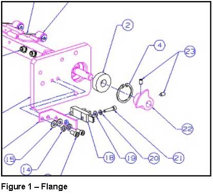
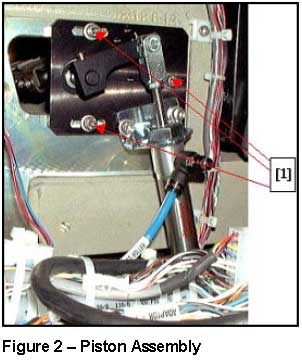
- Open and remove the three screws holding the Load Roller Flange.
- Using pliers, extract the Retaining Ring [4] from the shaft.
- Remove the bearing and retainers from the Load Roller Flange.
- Remove the Load Roller Flange.
To assemble the left Load Roller Flange:
- Insert the new Load Roller Flange.
- Insert the bearing and retainers.
- Assemble the Retaining Ring on the shaft.
- Insert and tighten the three screws that hold the Load Roller Flange.
- Insert the HP Flag and tighten the two retaining screws.
- Insert the air tube to the piston.
To disassemble the right Load Roller Flange:
- Remove the Cotter Pin [11].
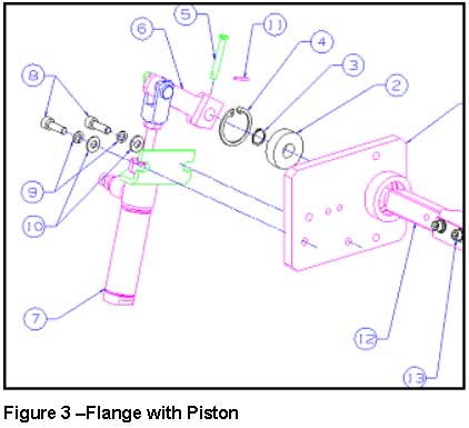
- Remove the Roller Arm Pin [5].
- Open and remove the two screws that hold the piston [8].
- Remove the piston [7].
- Open and remove the three screws holding the Load Roller Flange.
- Using pliers, extract the Retaining Ring [4] from the shaft.
- Remove the bearing and retainers from the Load Roller Flange.
- Remove the Load Roller Flange.
To assemble the right Load Roller Flange:
- Insert the new Load Roller Flange.
- Insert the bearing and retainers.
- Assemble the Retaining Ring on the shaft.
- Insert and tighten the three screws that hold the Load Roller Flange.
- Reinstall the piston.
- Insert and tighten the two screws that hold the piston.
- Insert the Roller Arm Pin [5].
- Insert the Cotter Pin [11].
Adjusting the Load Roller
- Connect the air pressure to the machine.
- Move the Tail Gripper until it is as close as possible to the Head Gripper.
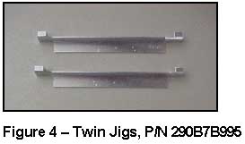
- On both sides of the drum, place a twin Jig (P/N 290B7B995), as shown in Figure 4, under the Tail Gripper.
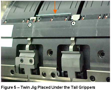
- Drag the Tail Grippers until they touch the Head Gripper, as shown in Figure 5.
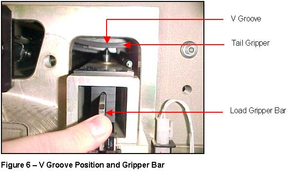
- Turn the drum until the V groove in the Tail Gripper is directly above the Load Gripper Actuator Pins, as shown in Figure 6, and push the Load Gripper Bar to lock the drum position.
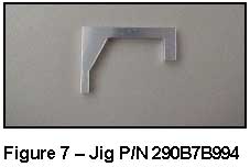
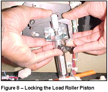
- Since the air pressure was turned off, use the jig (P/N 290B7B994) as shown in Figure 7, to lock the Load Roller Piston in position so that the rollers are almost touching the drum, as shown in Figure 8
- Release the three screws that hold the flange of the Load Roller Bracket on the left and right sides. (See Figure 2.)
- Push the Load Roller flange toward the Tail Gripper until the Load Rollers touches the jigs on both sides. First do one side, tighten the 3 screws that you loosened in step 7, and then do the other side.
- Remove the Piston jig.
- Release the drum by pulling the Gripper Bar.
- Turn the drum to enable you to remove the two twin jigs.
Powering Up the Machine
- Connect the air pressure to the machine.
- Adjust the HP Flag so that it is above and as close as possible to the HP detector entrance, and tighten the two screws.
- Connect the main power to the machine.
- Turn on the machine
- Start the application.
- Assemble the Laser Covers by securing the six screws.
- Manually close the side doors.
- Close the front door.
- Check that the machine is in Ready mode
| Part No. | Qty | Description |
| 290B2T801A | 2 | Lower Actuator Flange II |
| 290B7B995 | 2 | Twin Jigs |
| 290B7B994 | 1 | Jig |
| !FCO-DOC | 1 | FCO document |
| CAM | 30 |
| CEU | 30 |
| CAP | 10 |
| CJP | 10 |
| CMA | 10 |
| No Limit |
| DU | Month | QTY | Month | QTY | Month | QTY | |
| CAM | : | April | 30 | ||||
| CEU | : | April | 30 | ||||
| CAP | : | April | 10 | ||||
| CJP | : | April | 10 | ||||
| CMA | : | April | 10 | ||||
| Other | : |