Home | Contact Us | Submit Troubleshooting Info | Search | Help


    Output | Software Solutions | Proofing | Color, Screening and Calibration | Scanning | Digital Photography | Consumables | POS


Field Change Order #510F28441 - Vibration Detector Type 2

Description: The purpose of this FCO is to improve the reliability of the vibration sensors by replacing them, in a different location, with a newly designed version.

Prepared By: 42967

FCO Kit No: 510F28441

Comp. Level: N/A

Machine S/N: all

Catalog No: N/A

S/W Affected: N/A

Type of Change: Conditional

Estimated time to implement: 2hrs

Product Mgr: Nir Halup

Approval Date:

Product Support: Meir Dana

Approval Date: 29-Apr-2002

Customer Support Mgr: Assaf Zach

Approval Date:


  1. Reason For Change
    Over time, the Opto-Mech assembly compresses the shock absorbing pads, making them less effective. As a result, the vibration sensors are activated more often and are more difficult to adjust.

  2. Description of Change
    Change the location of the vibration sensors and add a newly designed vibration sensor assembly.

  3. Change Procedure

    Required Tools:
    • DVM
    • Allen keys
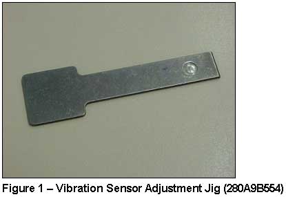
    • Vibration sensor adjustment jig (see figure 1)


    Installing the Vibration Sensor

    1. From the application, open the front door.
    2. Manually open the right and left side doors.
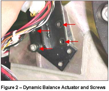
    3. Remove the spacer located under the dynamic balance actuator by removing the four screws on the dynamic balance actuator. (See Figure 2.)

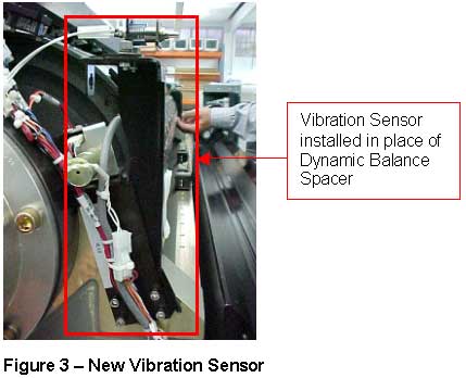
    4. Install the new vibration sensor under the dynamic balance actuator, instead of the spacer that you removed in step 3. (See Figure 3).

      Note: There are two vibration sensors installed on two types of brackets - wide and narrow:

      • Wide bracket - install on left side of machine.
      • Narrow bracket - install on right side of machine (Light Detector side).

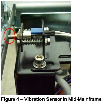
    5. Adjust the bracket so that the vibration sensor is in the middle of the mainframe (see Figure 4) and the bracket is as close to the drum as possible, and tighten the screws. The vibration sensor bracket has oval holes for adjustment.


    6. Repeat step 5 for the second bracket.
    7. Carefully cut the tie-wraps to release the vibration sensor wires from their current place, to enable them to reach the new vibration sensor connector.
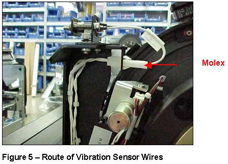
    8. Route the vibration sensor wires along the new bracket. (See Figure 5.)


    Adjusting the Vibration Sensor

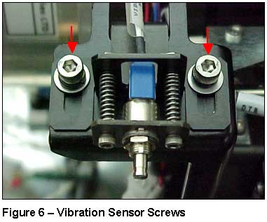
    1. Loosen the 2 screws that connect the vibration sensor to allow the vibration sensor to move freely. (See Figure 6.)


    2. Disconnect the molex connector from the vibration sensor. (See Figure 5.)
    3. Connect the DVM to the pins inside the molex connector on the side of the vibration sensor.
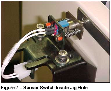
    4. Slide the jig under the vibration sensor, so that the sensor switch is inside the jig hole (see figure 7). In this case, the DVM indicates a short circuit - the vibration sensor is not activated.

    5. Slide the jig out so the sensor switch is outside the jig hole. The short circuit is disconnected and the vibration sensor is activated.
    6. Tighten the 2 screws to prevent movement of the vibration sensor and to prevent the shims from activating the vibration sensor.
    7. If the shim still activates the vibration sensor, loosen the 2 screws and repeat steps 5-6 until the sensor is no longer activated.
    8. Tighten the 2 screws to secure the vibration sensor in place.

  4. Test Procedure
    Expose a plate to verify that no vibration errors appear during drum rotation.

  5. Parts List
    PART QTY DESCRIPTION
    203A10030 20 MINI CABLE TIE 140MM
    203A10050 20 STNDR.CABLE TIE 170MM
    292A7B628 1 VIBRATION BRACKET RIGHT
    292A7B629 1 VIBRATION BRACKET LEFT
    374A00080 1 PACKING LABEL-WHT
    380A07061 5 SOC HD CAP STST10-24*1/2"
    382A13000 5 FLAT WASHER STST #10S
    382D13000 5 SPRING L/W ST ST #10L
    507A4E091 2 VIBRATION ASSY TYPE 2
    280A9B554 1 JIG-VIBRATION SENSOR ADJUST

  6. Attached Documentation
    None.

  7. Material Disposition
    Dispose of the spacer that was removed in step 3.

  8. Logistics
    Approved quantities:
    CAM : 30
    CEU : 30
    CAP : 10
    CJN : 10
    CMA : 10
    Other :  
    No Limit    

    Copyright © 2005 Creo Inc. All rights reserved. Confidential. Back to top.