Home | Contact Us | Submit Troubleshooting Info | Search | Help
Output | Software Solutions | Proofing | Color, Screening and Calibration | Scanning | Digital Photography | Consumables | POS
Home | Contact Us | Submit Troubleshooting Info | Search | Help
Output | Software Solutions | Proofing | Color, Screening and Calibration | Scanning | Digital Photography | Consumables | POS
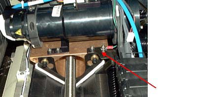
The carriage V block bracket has been replaced by a new type, which allows installation of a second oil bracket on the left side of the optic head. This FCO includes two oil brackets, one for each side of the optic head carriage.
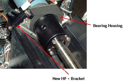
There are two types of HP detector Assemblies. They include the bracket housings.
If an engineer needs to replace the carriage HP, follow these instructions:
Adding an oil kit to the optic head carriage decreases friction between the
carriage surface and the V block. It also cleans the V block surface.
Add two oil kits, one for each side of the optic head carriage.
In order to add the second oil bracket (on the left side) to the carriage optic
head, you must replace the left lead screw bearing housing, the HP detector,
and the chain base of the carriage.
See How to clean and oil the V-block/carriage beam on all CIL devices.
|
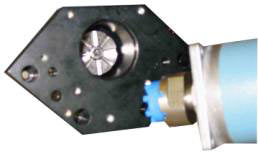
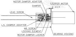
1. Disassemble the motor from the Lead Screw. |
 |
|
|
 |
| 280A9L161A |
CHAIN BASE-II |
|
| 291A2N300A |
NEW OILER BRACKET |
|
| 374A00080 | PACKING LABEL-WHITE |
|
| 380A09062 | SOC HD CAP ST1/4-20*1/2" |
|
| 382A16000 | FLAT WASHER STST 1/4" |
|
| 402-00105 |
Oil for the Oil brackets |
|
| 507A3D222 |
HOME POSITION ASSY-NEW |
|
None
None
20011209125856
20011218145755