Applies to |
|
- Lotem® 800
- Lotem Quantum
- Lotem Quantum Spectrum
- Lotem 400 with MCU
|
Priority = Next failure
Release date = 18 Jun 2003
|
Component |
|
Bar flag detector
|
Problem |
|
Electrostatic electricity that comes from plates/paper harms bar flag
detector through anodized bar flag and causes problems such as "Right/left
local does not respond.".
|
Solution |
|
Change the bar flag construction by adding a grounding cable to the loading
system bar. The new bar flag is made from two separated parts bonded together
with epoxy glue, one part is plastic and the other is stainless steel.
The following guidelines were used for the new bar flag design:
- Keep same weight and dimensions as the old one.
- Non-conductive material at upper part of the bar flag.
|
Time needed to
implement |
|
1 hour
|
Parts needed |
|
|
Part name
|
Qty
|
Part No.
|
| Grounding cable, L=2.5 M |
1 |
220-00208A
|
| Packing label - Wht |
1 |
374A00080
|
| Ext tooth L/W St St #8 |
5 |
382J11000
|
| Envelope 16 cm x 21 cm air bubbles |
1 |
391I60617
|
| Bar flag assembly |
1 |
500-04777A
|
| Document - Antistatic bar flag assembly |
1 |
719-01636 Rev C
|
|
Procedure |
|
Bar Flag Assembly
- Open the front door of the platesetter.
- Release the cassette from the platesetter.
- Close the application, and shut down the platesetter.
- Open the XY bar cover.
- Remove the bar flag detector:
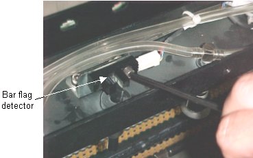
- Remove the bar flag.
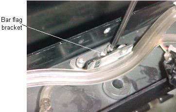
- Release the bar flag bracket by removing the two screws, as shown
below. Make sure the securing nuts will not fall down.
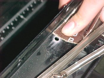
- Using either sand paper or a metal brush, file the paint
from under the bracket location (very important!!):
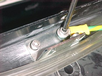
- Reattach the bracket to the XY bar using the left screw.
- Insert the other (right) screw through the supplied grounding cable
(the cable suffix has two sizes, choose the correct one) and connect
it to the bracket:
Note: Use Loctite® 242.
Lotem 800
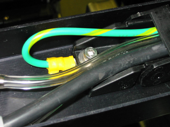
Lotem 400
- Open both the X and Y plastic chain covers.
- Route the grounding cable through the XY bar, the Y-axis plastic chain,
and then through the X-axis chain:
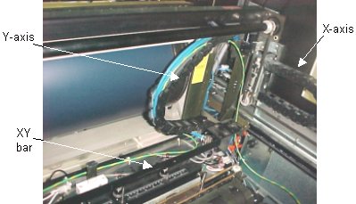
- Secure the grounding cable with tie wraps, making sure
it does not interfere with the X and Y movements.
- Close the X and Y chain covers.
- Connect the other side of the grounding cable to the main frame:
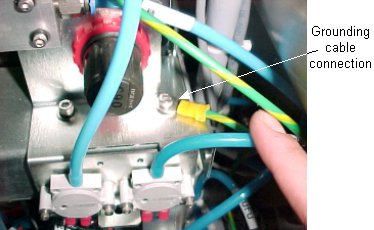
Lotem 800
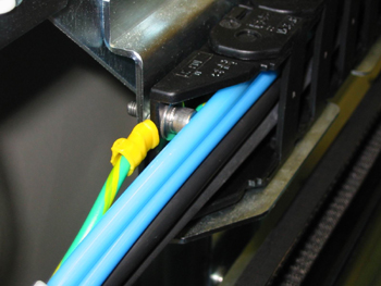
Lotem 400
- Tie the rest of the free grounding cable, securing it so
that it does not interfere with the loading operation.
- Insert the new bar flag:
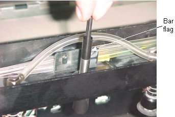
- Reassemble the bar flag detector, making sure not to overly
tighten the screw:
Test Procedure
- Push the new bar flag up and down, making sure it moves freely.
- Test the new grounding connection by using a multimeter (in resistor
mode) between the bar flag bracket and the main frame. Make sure the
grounding is good.
- Power up the platesetter.
- Start up the application.
- Insert the loading cassette into the platesetter.
- Open the bar flag detector dialog from the Lotem Controller.
- Move the bar flag up and down. Make sure the detector changes status.
- Perform plate loading with open doors, and make sure that the new
grounding cable does not interfere with the normal operation of the
XY loading system.
- Close the XY bar black cover.
- Close all opened doors.
- Return to working status.
|
|
Technical
contact |
|
Meir Dana
|
Date submitted |
|
19 Jun 2003
719-01636 Rev C
|

