Field Change Order - Magnetic Sensor Loading Cassette
Sammy Avisror
Tue 03 August 1999
News Version:
There is a new P/N for the loading cassette which includes the FCO Magnetic sensor -
Loading cassette. The P/N is 507F2D449.
The P/N of the old cassette (with out the magnet sensor implemented) is 507F1L036
This FCO includes all parts needed to upgrade 3 loading cassettes and upgrade that
needed for 1 Lotem.
As soon as you updating the cassette with this FCO you must update all the loading
cassette that the customer has on site.
In order to implement all loading cassettes upgrade in the field we will send the FCO's to
the field as soon as we have all FCO's Qty that needed .
Prepared By: S. Avisror
FCO Kit No.: 25560
Comp. Level:
Machine S/N: Lower then 9930xxxxx
Catalog No: 510F25560
S/W Affected: N/A
Type of Change: Mandatory
Total Number of Pages 10
Product Mgr: Nir Halup
Approval Date: 1/8//99
Product Support: Sammy Avisror
Approval Date: 1/8//99
Customer Support Mgr: Kuty Paperny
Approval Date: 1/08/99
Note: There is a new P/N for the loading cassette which includes this FCO. The P/N is
507F2D449.
The P/N of the old cassette (with out the magnet sensor implemented) is 507F1L036
This FCO includes all parts needed to upgrade 3 loading cassette and upgrade that needed
for 1 Lotem.
As soon as you updating the cassette with this FCO you must update all the loading
cassette that the customer has on site.
Reason For Change - Improve the reliability of the cassette interlock with new type
magnetic sensor.
Description of Change - This FCO is intended to replace the existing interlock mechanism
on the plate cassette.
Change Procedure
Required Tools:
Drill (electrical, air operated or rechargeable)
4mm (0.157 inch) and 6mm (0.236 inch) high speed drill bits.
Set of Allen keys.
Small piece of cardboard for mixing glue.
2 pieces of wood or any other material on which to place cassette.
locktite glue-#242.
Attaching Actuator Assembly to Cassette
Empty cassette from all plates.
Close lid and secure latches on both sides.
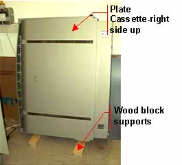
Lift cassette off of its base and place on the left side (so that right side is
uppermost) on the 2 wooden blocks so that it does not press on the latch.
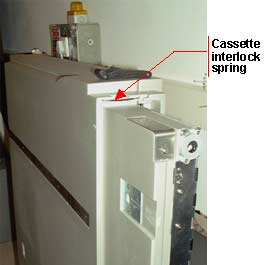
Remove cassette interlock spring.
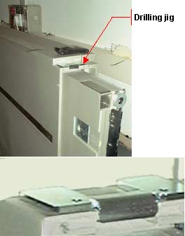
Press drilling jig in place, ensure that it is flush with the outer edge and pressed
down firmly.
Drill 2 holes using a 4mm drill bit. Remove the jig and enlarge the holes using the 6mm
drill bit.
Clean the two holes from particles.
Ensure area around holes and inside is clean and clear of any foreign objects before
adding glue.
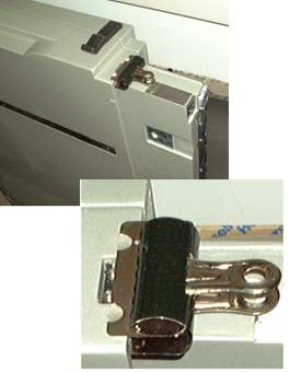
Clamp actuator assembly in place using bulldog clamp supplied in kit.
Mix required amounts of glue from both tubes on cardboard square. Ensure
there is enough to fill both holes
Pour glue into holes and press down with wooden sticks so that glue fills the holes
completely, remove excess glue that overflows.
The initial drying period is 15minutes and the clamp must not be removed during this time.
For final drying period is one hour before using the cassette.
Implement the same process for all the loading cassettes on site. You have in this
FCO’s 3 actuator assembly for 3 loading cassettes.
Installing Sensor Assembly
The installation of the Sensor Assembly comprises two steps:
Remove 2 retaining screws and disconnect interlock assembly from frame.
Disconnect 4 cables attached to the interlock assembly.
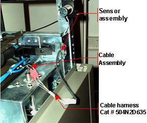
Insert Sensor Assembly
Attach sensor assembly to frame using the same holes as used for interlock assembly.
Spread locktite glue on screws before tightening (use screws provided in kit).
Connect cable harness adapter assembly to 4 cables from interlock assembly, connecting
matching colors in each case.
Slide also shrinks wrap casing over the cable connections. Secure the cable
to eliminate damage by the loading cassette.
Connect cable assembly to sensor assembly.
Replace and close all covers.
Test Procedure – Open the Cassette interlock detector and check that the status of
the detector is changing from off to on.
Parts List -
Actuator assembly (for Cassette)
507A2D676
3
Sensor assembly (for machine)
506A2D675
1
Harness assembly
504N2D635
1
Bulldog clip
290A2N309
1
Drilling jig
290A2N226
1
Epoxy glue
480C10045
1
Wooden tooth picks
457F41100
2
Allen screws 4-40/5/16
380A01032
2
Spring washers #4.
38205000
2
Cable holders
203C10020
3
Harness holder
203A10050
10
Packaging
391A70210
1
Attached Documentation – N/A
Material Disposition – You can dispose the interlock.
Logistics - The following FCO kits need to order by the Subsidiaries:
STA - 82
STE - 82
STAP - 12
STN - 12
STMA - 12
Questions & Answers
Hi All, recently we shipped the magnetic sensor to the field for upgrading
the Loading cassettes.
Reason For Change - Improve the reliability of the cassette interlock with
new type magnetic sensor.
The FCO P/N - 510F25560
The following comments to Ido from STA which sound like he is the first one that
implement the FCO.
Since we sent most of the FCO's to the field I will use the following as
comments to the entire field.
-----Original Message-----
From: Ido Shatzky
Sent: 05 October 1999 20:35
To: Sammy Avisror
Cc: Frank Radlof; Efraim Eller; Jim Buczynski; Merav Cohen; Rich Thies;
Sammy Avisror; Zelik Leibovitch
Subject: the new FCO "magnetic sensor - loading cassette"
Hi Sammy
I did today the FCO of "magnetic sensor - loading cassette" in WE
and here are my remarks:
We need a cheater. is the red piece of metal that was attach to the kit is for the cheater? the cheater is a red
bracket with a magnet. The P/N of the cheater is 507A2D738. The cheater is
part of the FCO and will be arrive with each Lotem that send from the
assembly line. See the following word file for positioning the Cheater.
If yes how to install it?, we need to add the new cheater to the
"spare part on site"
Can we add another sensor for the 4th cassette, just in case that we have
four cassette on site, it will be a waste of money to order another kit just
for one cassette sensor. We already shipped all of the FCO's to the field.
If you need actuator for the forth cassette (fifth ,,,) place order for
507A2D676.
In one of the cassette we were needed to file the cassette, to have room for the jig, I think it should be written
in the procedure that if the jig is not fit you should file the cassette. O.K.
I think we should add another picture, of the jig mounted on the cassette,
from top view.
It will be easier to understand how to mount the jig on the cassette.
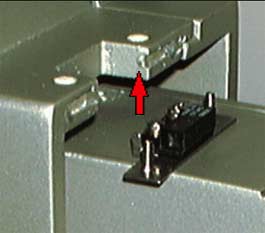
Between step 7 and 8, please add the explanation how to put the sensor inside the cassette, you have only picture with
out explanation. Follow the arrow direction to place the magnet actuator and
use the bulldog clamp to hold the actuator to the cassette.
Step 10, it is very difficult to clean the glue from bulldog clamp, and if
you don't do it right it might glue the clamp also.
Frank found a very nice idea, put film between the clamp and the hole, then
the glue can stick only to the film and not to the clamp. Nice TIP can we
change the position of the cassette from vertical to horizontal after we put
the glue?, or we need to wait few minutes? if yes how long? You need to wait
15 minutes. See step 10 in the FCO doc.
Please add this restriction, if there is any, to the procedure.
In "remove cassette interlock" why you need step 2 "remove
upper front right side panels"?
The shrink that you send, were and how to warp it?, it is very difficult
to slide all the four connector inside, do you what us to cut it to four
pieces for each connector? please add picture
When we going to have NEW machine with the magnetic sensor install on
them? lOTEM s/n 9938xxxxxX
When we going to have NEW cassette with magnetic sensor? The loading
cassettes that shipped from the cassette vendor from last week 1/10/99 are
already with the magnet sensor.
Do we going to ask the filed to do it as a mandatory FCO, so all the
machine/cassette will be the same?. We are strongly recommend to implement
this FCO. You can do it when you have open call, in order to reduce calls on
site. (MTBV)