Procedure
|
|
This procedure includes the following steps:
Pre-installation site
inspection
Before implementing this FCO, you need to go to the customer site and
verify that all site preparations have been properly completed by the
customer according to the specifications listed in Universal
Debris Removal Cabinet (UDRC) Site Preparation Guide (pdf), and those
listed in this FCO.
Note: All electrical work must be completed by a qualified
electrician.
In addition, you need to verify several details about the
customer's machine and, in some situations, order additional parts.
For complete information about specifications and the machine
details to verify, see:
Compressed air supply
specifications
In addition to the site preparations listed in Universal
Debris Removal Cabinet (UDRC) Site Preparation Guide, the following
compressed air supply specifications must be met before the UDRC can be
installed:
Note: Verify that Compressed
Air Filtration Unit - 510P1R129 has been installed on this machine.
If it has not been, order and install the compressed air filtration unit
before proceeding.
- Pressure: 8 bars (~120 psi)
- Capacity: 17 CFM (minimum)
- Humidity: dew point of 3°C (37°F)
- Particles: 1 micron, 1mg/m3 (maximum)
- Oil: 0.01 mg/m3 (maximum)
Additional details
Verify the details listed below and order the required
additional parts before installing the UDRC.
- Verify the type of lens that is installed on the customer's
machine by visually checking the lens. The following picture
shows the differences between the three possible lens types:
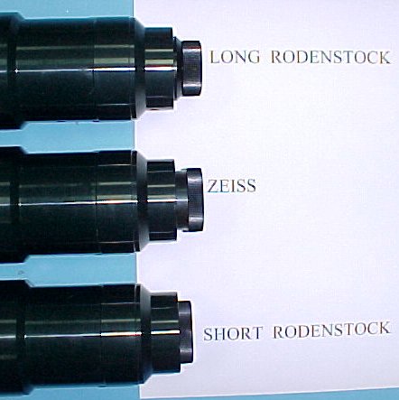
- If a Long Rodenstock or Zeiss
lens is installed, when you implement this FCO you
will install the Type I nozzle (p/n 507C3E963) that
is included in this kit.
- If a Short Rodenstock lens is
installed, order a Type II Nozzle (p/n 507B4E237)
before implementing this FCO.
- Verify whether the machine includes a
comp level 'O' (or higher) CTP power distribution board. If
it does not, order a CTP power distribution board
(p/n 503C2L049Q).
Important: Install the CTP
power distribution board before implementing this FCO.
- Verify the PC controller software
version (version 3.20.01 or higher must be installed before
this FCO can be implemented). If version 3.20.01 or later is
not installed, upgrade the software.
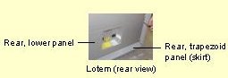
- Verify the type of rear trapezoid panel that is installed on
the machine. If it is the regular type without a vacuum tube
hole, order the rear trapezoid
panel, (p/n 510P1R070) before implementing this FCO.
The picture below shows the section of the trapezoid panel
with the vacuum tube hole.

Preparing the machine for
installation
- Verify that:
- All specifications have been met, as described in Pre-installation
site inspection.
- All required, additional
parts have been ordered as described in Additional
details.
- Compressed
Air Filtration Unit - 510P1R129 has been installed.
- The distribution board (comp
level 'O' or higher) has been installed, as
required.
- The PC controller software has
been upgraded to version 3.20.01 or later, as
required.
- From the PC controller, .
- From the PC controller, open the front door and the rear
door.
- Manually open the right door, remove the 6 screws that
secure the black laser cover in place and remove it from the
machine.
- Repeat step 3 on the left side.
-
- Rear trapezoid panel
- Rear upper panel
- Rear lower panel
- From the rear of the machine, disconnect the three unloading
tray motor connectors, remove the 6 screws that secure the
unloading tray in place, and then remove the unloading tray
from the machine.
- In the PC controller, close the Lotem application.
- Close the circuit breaker in the distribution box.
- Unplug the main power cable from the main power supply.
- Discontinue the air supply to the machine by closing the air
pressure valve on the wall air pressure unit.
- from the cable chain.
- Remove the cable chain from the machine, as follows:
- Remove the two cable chain securing screws from the
upper cable chain bracket (shown below).

- Carefully remove all cables and fibers from the
inside of the cable chain.
- Remove the 2 cable chain securing screws from the
lower cable chain bracket, and then remove the black
cable chain from the machine.
- Remove the two cable chain bracket
securing screws from the upper bracket, and remove the
bracket from the machine.
- Repeat step 14 on the lower bracket.
- Install the new upper cable chain bracket
(p/n 280A9L160) and the lower cable chain bracket
(p/n 280A9L161B) in the machine. Secure them in place
using the screws that you removed in steps
14 and 15.
Note: Be sure to apply Loctite™ to
each screw.
- Verify
chassis type and then continue as follows:
Installing the debris removal kit in
machines with an older type chassis
- From the rear of the machine, locate the black plastic tray
that divides the upper and lower portions of the machine
(just under the Optomec).
- Drill a 25 mm hole in the left side of the tray (on your
right), just behind the laser fiber tube, as shown below.
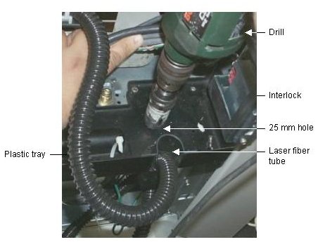
- Insert the 3/4 inch vacuum hose (p/n 344F10115) into the 25
mm hole that you just drilled, thread it through the hole to
the lower compartment of the Lotem, and route it over the
L-box and the D-box to the middle of the machine as shown
below.
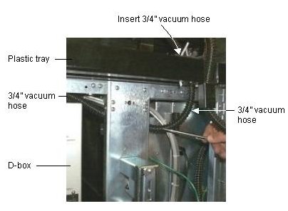
- Locate the 3/4 inch - 1 1/2 inch fitting (p/n 290B2M813),
attach it to the lower end of the 3/4 inch vacuum tube (the
one that you just routed over the D-box), and then secure it
in place using the supplied hose clamp (p/n 388L10035).
- Locate the 1 1/2 inch vacuum hose (p/n 344F10120) and attach
it to the 1 1/2 inch end of the fitting that you installed
in the previous step. Secure it in place using the supplied
hose clamp (p/n 388B28000).
- Locate the nipple out assembly (p/n 291A2N219), and then
secure it to the lower right rear corner of the machine (on
your left), as shown below.
Note: Use the supplied 1/4 inch screws,
spring, and flat washers. Be sure to apply Loctite to each
screw.
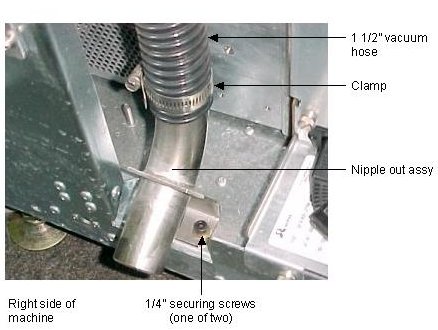
- Attach the other end of the 1 1/2 inch vacuum hose to the
upper part of the nipple you just installed and secure it in
place using the supplied hose clamp (p/n 388B28000), as
shown above.
- Install the debris collection nozzle as described in Installing
the debris collection nozzle.
Installing the debris removal kit in
machines with a newer type chassis
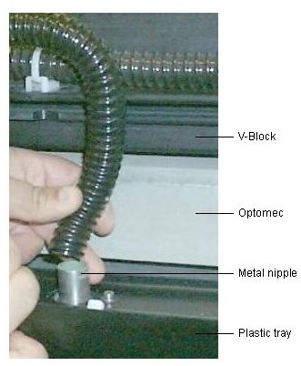
- Locate the 3/4 inch vacuum hose (p/n 344F10115), and then,
from the rear of the machine, attach one end to the metal
nipple on the chassis (shown below) and secure it in place
using the supplied hose clamp (p/n 388B2800).
Note: If you cannot attach the vacuum
hose to the metal nipple, remove the nipple from the machine
by removing the two securing screws, attach the vacuum hose
to the nipple and secure it in place using the hose clamp,
and then reinstall the nipple. Be sure to apply Loctite to
each screw.
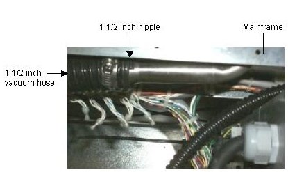
- Locate the 1 1/2 inch vacuum hose (p/n 344F10120), and
attach it to the 1 1/2 inch nipple underneath the mainframe.
Secure the vacuum hose to the nipple using the supplied hose
clamp (p/n 388B28000), as shown below.
- Locate the nipple out assembly at the lower-right rear
corner of the machine (on your left). Attach the other end
of the 1 1/2 inch vacuum tube to this nipple and secure it
in place using the supplied hose clamp (p/n 388B28000),
as shown below.
Note: If the nipple out assembly is not
installed, locate the nipple out assembly (p/n 291A2N219),
and use the supplied 1/4 inch screws, spring, and flat
washers to secure it to the lower-right rear corner of
the machine (on your left), as shown below. Be sure to apply
Loctite to each screw.
- Install the debris collection nozzle as described in Installing
the debris collection nozzle.
Installing the debris removal kit in
machines with an Omron chassis
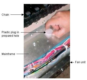
- From the rear of the machine, locate the prepared hole in
the mainframe, and remove the plastic plug from this hole
(shown below).
- Locate the plastic sleeve (p/n 290F9B892), place the sleeve
in the prepared hole, and use a plastic hammer to tap the
sleeve into the hole.

- Insert the 3/4 inch vacuum
hose into the plastic sleeve in the mainframe and pass it
through the sleeve to the lower compartment.
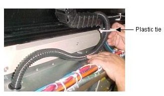
- Use a plastic tie to secure the 3/4 inch vacuum hose to the
other cables, as shown below.
- Locate the 3/4 inch - 1 1/2 inch fitting
(p/n 290B2M813), attach it to the lower end of the 3/4
inch vacuum tube, and secure it in place using the supplied
hose clamp (p/n 388B2800), as shown below.
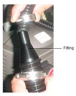
- Locate the 1 1/2 inch vacuum hose (p/n 344F10120) and
attach it to the 1 1/2 inch end of the fitting that you
installed in the previous step. Secure it in place using the
supplied hose clamp (p/n 388L10035), as shown above.
- Locate the nipple out assembly on the lower-right rear
corner of the machine (on your left, shown below).

- Attach the other end of the 1 1/2 inch vacuum hose to the
upper part of the nipple that you just installed and secure
it in place using the supplied hose clamp
(p/n 388B28000), as shown above.
- Install the debris collection nozzle as described in Installing
the debris collection nozzle.
Installing the
debris collection nozzle
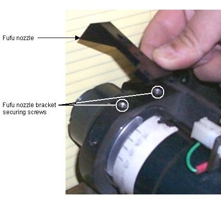
- From the rear of the machine, remove the two fufu nozzle
bracket securing screws (shown below), and remove the
bracket from the optic head.
Note: Leave the fufu tube in place.
- Install the new cable chain (p/n 203C10085).
Note: Do not put the cover onto the
chain.
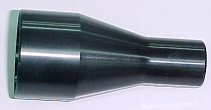
- Locate the relevant nozzle according to the type of lens on
the optic head:
- Long Rodenstock: Type I nozzle (p/n 507C3E963)
- Zeiss: Type I nozzle (p/n 507C3E963)
- Short Rodenstock: Type II nozzle (p/n 507B4E237)
- Install the relevant nozzle on the end of the optic lens, as
follows:
- From above, place the nozzle over the lens, and
press the nozzle toward the optic head until it is
flush with the lens protector.
- Secure the nozzle in place by tightening the two
nozzle securing screws on top of the nozzle (shown
below).
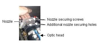
- Insert the two supplied 8-32 x 3/8 inch screws and
flat and spring washers into the additional nozzle
securing holes (shown above) and tighten them.
Note: Be sure to apply Loctite
to each screw.
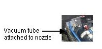
- Attach the end of the 3/4 inch vacuum hose to the
3/4 inch nipple on the nozzle, as shown below, and
then secure it in place using the supplied hose
clamp (p/n 388B2800).
Note: The 3/4 inch vacuum hose
is the one that you previously installed.
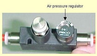
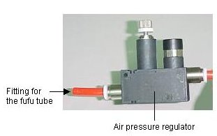
- Attach the fufu tube to the fitting on the air
pressure regulator that is attached to the nozzle
(shown below).
Note: If the fufu tube is too
long, cut it, as required.
- Verify whether the machine supports a vacuum sensing
option. Then:
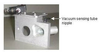
- If the machine supports a vacuum sensing
option, attach the vacuum sensing tube to
the vacuum sensing tube nipple on the top of
the nozzle (shown below).
- If the machine does not support a vacuum
sensing option, remove the nipple and plug
the inlet with the supplied plug
(p/n: 344B13050, included with the
ablation nozzle assembly,
p/n 507C3E963).
- Place the following items into the cable chain according to
the diagram below:
- Blue 1/4 inch fufu tube
- 3/4 inch air hose
- Power cable
- Vacuum sensor tube, if supported
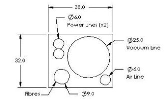
Note: The components in the cable chain
should lay flat and not be tangled.
- Place the cable chain cover on the cable chain, and press it
down to secure it in place (it should snap into place).
- Manually rotate the drum and make sure there is sufficient
clearance between the tail grippers and the nozzle.
- Inspect the right-most spoiler (on your left) and verify
whether it is the same as (p/n 290B2P030A). If
it is, proceed to the next step. If it is not, remove it and
install the new one, as follows:
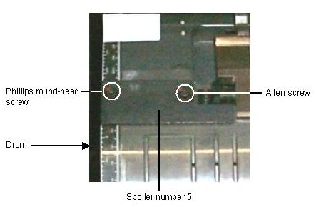
- Remove the two spoiler securing screws (one Philips™
round-head screw and one Allen™ screw, shown
below), and remove the spoiler from the machine.
- Secure the supplied spoiler (p/n 290B2P030A) in
place using the two screws previously removed. Be
sure to apply Loctite to each screw.
- Install the light detector hood (p/n 280B2M807) supplied
with this FCO kit, as follows:
- Disconnect the connector on top of the (shown below).
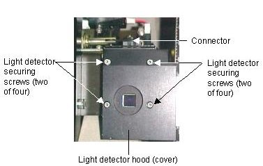
- Remove the four light detector securing screws
(shown above), and carefully remove the light
detector assembly from the machine.
Note: Do not drop the light
detector or touch the light detector lens.
- Remove the light detector hood (cover) from the
light detector.
- Clean the light detector lens using one of the
following, soaked with alcohol:
- Rice paper
- Special lens-cleaning paper
- Q-tip
- Clean the light detector lens again, using a clean
piece of paper or Q-tip (as described in the
previous step) soaked with acetone.
- Place the supplied light detector hood on the light
detector, and secure the light detector assembly to
the machine using the four
screws that you previously removed.
Note: Be sure to apply Loctite
to each screw.
Installing the
Universal Debris Removal Cabinet (UDRC)
- Position the UDRC (p/n 506A01506A) as close to the rear
of the machine as possible.
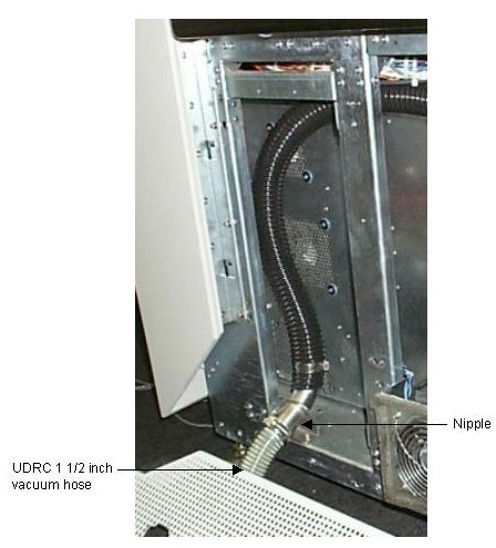
- Attach the 1 1/2 inch vacuum hose that is connected to
the UDRC to the nipple at the lower-right rear of the
machineand secure it in place using a hose clamp
(p/n 388L10035), as shown below.
- Verify whether the machine you are working on is a LOCAL2 or
a LOCAL3 machine. Then, connect the relevant control cable,
as follows:
- In LOCAL2 machines, connect the control cable
(p/n 504L3E849) to the two-pin J5 Molex
connector on the distribution box (the connector is
labeled J5 SOLENOID).
Note: Route the control cable
along the vacuum hose.
- In LOCAL3 machines, connect the control cable
(p/n 504L3E848A) to the Molex cable near the
E-box (the cable is labeled ABL).
- Connect the Vacuum Unit to the power supply.
- Reconnect the main power supply.
- Open the air supply valve on the wall air supply unit.
Note: Verify that the air pressure
level is at least 6 bar.
- Perform start up.
- In the PC controller, set the values for the following
parameters:
Note: Click Utilities >
Hardware to access these parameters.
- Others/LOTEM800V/I/O Objects/Distribution
card/Solenoid Switch/Optical Head Suction:
- Hold Pwn Value = 250 (Default 150)
- Max Allowed Sol Activation Time =255
(Default 3)
- Open = 0 (Default 0)
- App Auto Off Time = 0 (Default 1)
- Others/LOTEM800V/EXPOSE:
- Lens Air Suction Enable = 1 (Default 0)
- In addition, if the machine you are working on is a
LOCAL3 machine, set these values for the following
parameters:
- Others/LOTEM800V/I/O OBJECTS/LOCAL
3/VALVE/Lens Air suction:
- Make sure the Valve Number is 8 and
it's connection to the Left Local
Card
- Lens Air Suction App HP Detector =
None
- Lens Air Suction App End Detector
Name = None
- Others/LOTEM800V/IO OBJECTS/LOCAL
3/DETECTORS/Lens Air Filter OK
Detector/Detector Active State = 0
(Default = 1).
- Others/LOTEM800V/IO OBJECTS/LOCAL 3
DETECTORS/Lens Air Vacuum OK
Detector/Detector Active State = 0
(Default = 1).
- Others/LOTEM800V/PROTECTORS/Drum
Motor Protector/Open = 1
Testing functionality
- Insert cheaters into interlocks, as required.
- From the PC controller, .
- Verify that the is set to 40–45 psi.
- From the PC controller, and verify that suction occurs at
the debris collection nozzle.
- Feel for leaks at all vacuum hose unions.
- From the PC controller, . Watch the nozzle as
the optic head passes the light detector and verify that
there is adequate clearance and that they do not collide.
- Adjust the focus mechanical stopper by sending the motor to
position 500, attaching the stopper to the optic tube and
tightening the screws.
- From the PC controller, .
Watch the optic head as it moves, and verify that there is
adequate clearance between the optic head and the unloading
tray, that they do not collide, and that the vacuum hose
does not come into contact with the tray at any point.
- From the PC controller, move the
carriage to the middle of the drum. Then, manually rotate
the drum and verify that the spoilers do not touch the
nozzle.
Note: It is extremely important
that the head gripper and tail gripper spoilers do not come
into contact with the nozzle.
- Load a 0.3 mm plate and repeat step 9.
Note: Do not remove the plate.
- Remove all cheaters and complete the following:
Note: Be sure to apply Loctite to each
screw.
- Replace the unloading tray.
Note: Be sure to reconnect the
three unloading tray motor connectors.
- Replace the black laser covers on the right and left
sides of the machine.
- Replace all panels.
Note: Remember to install the correct
rear trapezoid panel (p/n 299A9B172).
- Close all doors.
IMPORTANT! Do not proceed until all
panels are properly replaced and all doors are closed.
- From the PC controller, rotate the drum at a rate of
900 RPM.
IMPORTANT! Be
prepared to stop the machine immediately either from the PC
controller, or using the main circuit breaker.
- While the drum is rotating, .
While the carriage is moving, listen carefully for any
sounds that may indicate malfunction, such as the nozzle
colliding with something. If you hear anything of this sort:
- Stop the machine immediately.
- Open the rear door and check the clearance between
the debris collection nozzle and other machine
parts.
|


 To
remove the cable chain cover, insert a flathead screwdriver under the cover and
pop it off of the cable chain.