Applies to |
|
- Lotem® 800 Family
- Lotem 800 II
- Lotem Quantum
|
Priority: Next failure
Release date: 22 Jun 2004
Type of change:
|
Component |
|
Single loading cassettes and dual
loading cassettes. |
Problem |
|
The existing air nozzles on the platesetter can damage the plastic washers
inside the cassette air fitting assemblies and eventually lead to plate
and paper separation failures.
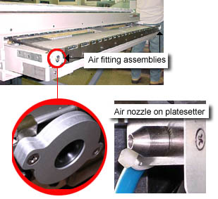
The damage results from:
- Prolonged use of the loading cassette over a long period of time.
- Mishandling of the loading cassette.
- Sharp nozzles cutting into plastic washers.
- Uneven floors causing the air nozzles to enter the assemblies slightly
off center.
In addition, the springs inside the air fitting assemblies can often
break.
All these factors can lead to deterioration in the airflow between
the platesetter and the loading cassette.
|
Solution |
|
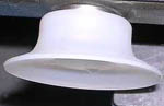
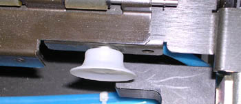
On the platesetter: Replace the air nozzles with silicon suction
cups:
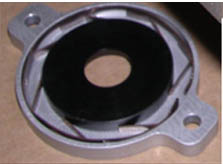
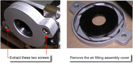
On the loading cassette: Remove the air fitting covers containing
the springs and plastic washer:
|
Time needed to
implement |
|
15 minutes. |
Parts needed |
|
| Part number |
Part name |
Quantity |
| 380G01010 |
PHIL FLT HD STST 4-40*3/16" |
8 |
| 500-00692A |
Air connector assembly |
2 |
| 347M25798 |
Speed cont. valve 6mm |
2 |
| 719-00161A |
FCO document |
1 |
|
Procedure |
|
Before you begin: In Lotem Controller, remove the loading
cassette from the platesetter.
On the platesetter, repeat the following procedures for both sets
of air nozzles.
- Using a pair of pliers, rotate the air nozzle in a counter clockwise
direction. Simultaneously, on the opposing side of the panel, insert
a screwdriver into the screw of the air fitting. The screwdriver not
only acts as a resistance to the pliers, but more importantly it also
prevents the plastic air nozzle seal from falling off:
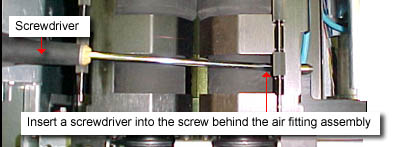
Do not remove the screwdriver until the nozzle has been replaced.
- Continue rotating the air nozzle until it can be removed and then
dispose of the nozzle.
- Apply Loctite® 242 onto the suction cup screw (p/n 500-00692A)
and then screw the silicon suction cup onto the thread vacated by the
air nozzle:
- From the right side of the platesetter (when facing the loading system),
remove the side panel and the metal cover.
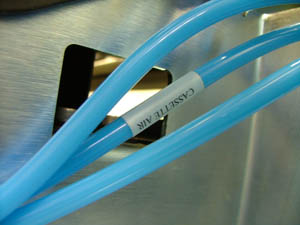
- Locate the two blue air cassette tubes:
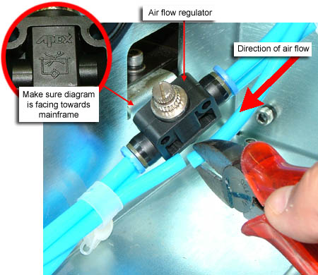
- Cut one of the air tubes in the middle and insert the two tube ends
into the open holes located on the sides of the airflow regulator. Make
sure the diagram on the back of the airflow regulator is facing towards
the mainframe:
Note: If the airflow
regulator is incorrectly attached, the air will remain constant and
impossible to adjust.
- Repeat the previous step for the second cassette air tube.
- Fully open both air regulator valves.
On the loading cassette, repeat the following procedures for both
sets of air fitting assemblies.
- Extract the two screws on either side of the air fitting assembly
and remove the cover containing the plastic washer and the spring:
- Dispose of the cover.
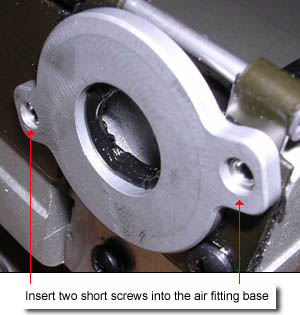
- Apply Locktite 242 to the two short screws (p/n 380G01010) included
in this kit, and then insert the screws into the holes on either side
of the air fitting base:
- From within Lotem Controller, release the cassette locking pins.
- Insert the loading cassette back into the platesetter.
- Make sure the platesetter reaches Ready mode.
|
Test Procedure |
|
- Load several plates with differing sizes and find
the optimum airflow:
- Start with the smallest plate size and begin to adjust the airflow at the same time as the XY system is picking up the plates
from the cassette.
- Continue to adjust the airflow regulator valve until the optimum
airflow is reached - meaning the paper will not fold in on itself
and be pushed to the back of the cassette.
- Load the largest plate and make sure the adjusted airflow is
sufficient for achieving good paper plate separation. If it is not
sufficient enough, repeat step 1.
- After defining the optimum airflow, tighten the air regulator nuts.
- Reinstall the metal cover and side panel.
|
Logistics |
|
Approved quantities:
| CSC |
Quantity |
| CAM: |
50
|
| CEM: |
150
|
| CAP: |
50
|
| CJP: |
30
|
Schedule supplies for first lots:
| Schedule |
CAM |
CAP |
CJP |
CEM |
| April |
25 |
25 |
15 |
60 |
| May |
25 |
25 |
15 |
60 |
| June |
0 |
0 |
0 |
30 |
Lead time: 2 months for additional quantities |
Material disposition |
|
- Air nozzle.
- Air fitting assembly cover, including the washer and spring.
|
|
Document number |
|
719-00161A - Rev B |
Technical
contact(s)
| |
Itai
Peperovich
Product Support Manager: Yaron Soffer
Approval Date: 22 Jun 04 |

