

Home | Contact Us | Submit Troubleshooting Info | Search | Help
Output | Software Solutions | Proofing | Color, Screening and Calibration | Scanning | Digital Photography | Consumables | POS
Home | Contact Us | Submit Troubleshooting Info | Search | Help
Output | Software Solutions | Proofing | Color, Screening and Calibration | Scanning | Digital Photography | Consumables | POS
| Lotem 800 Installation Guide Laser and Safety Precautions |
Enclosures
Interlocks
Optical Fibers
Optical Head
L-Box
Warning Labels
|
|
Use of controls and/or adjustments, or performance of procedures other than those specified in this manual may result in hazardous radiation exposure. |
The Lotem 800 is equipped with a highly hazardous multi-beam laser system that exposes the media. However, it is a Class 1 laser product, according to IEC825-1 and the USA 21 CFR 1040. This implies that the operator cannot access hazardous laser radiation, providing that the user and service safety precautions are followed.
|
|
The laser beam and radiation of the platesetter are invisible to the eye, but hazardous to the eye and skin. Even brief exposure of the eyes to the laser radiation or beam, or its reflections from shiny or matte objects may cause permanent loss or permanent degradation of eyesight ! |
 |
Whenever in doubt, the platesetter should never be operated until it is checked and approved for operation by an authorized service engineer ! |
|
|
If you must enter the room where the platesetter is located when the platesetter is on, and you suspect that any of the above mentioned precautions was somehow violated, then you must disconnect the power supply to the platesetter before entering the room ! |
Enclosures
Together with the Laser interlock system, the platesetter enclosure is designed to protect anyone in the platesetter vicinity from exposure to the laser radiation by enclosing the laser radiation within the platesetter. The enclosure includes the external doors and panels, and the internal protective barriers. The internal protective barriers prevent the laser radiation from escaping through the platesetter loading/unloading openings and through the ventilation openings on the side doors or lower panels. This protection depends upon the completeness and correct assembly of the outer enclosure and the internal protective barriers.
Note: The opening of the two upper doors is controlled by a spring loaded mechanism. Make sure your head is not near the door when opening the door.
|
|
After performing any service activity and before switching on the platesetter, the service engineer must check and ensure that all external and internal enclosures are complete, not broken or cracked, and properly assembled to the platesetter. |
|
|
If the platesetter is on and the enclosure is damaged or incomplete, and even with the doors closed, then laser radiation of up to several watts at a wavelength of 810-860 nanometer may be present. Even brief exposure of the eye to this radiation or its reflection from shiny or matte objects can cause permanent degradation or permanent loss of eyesight ! |
Interlocks
Interlock switches are designed to disconnect power from all the Laser sources and from mechanically hazardous parts when one of the above doors is opened or one of the panels is removed. See the following interlock table and figures.
|
|
The service engineer is forbidden under any circumstances to defeat any of the Laser interlock switches. |
For each interlocked door or panel, the motor and actuators (mechanical) interlock consists of one interlock switch. The laser interlock consists of two switches placed together in a designated metal box.
The service engineer is allowed to defeat the motors and actuators interlock switches, only after taking appropriate safety measures.
Important Note: If you must defeat the motor interlocks, you are not allowed to use any other means except the dedicated cheaters (Scitex No. 290B8L064) that are supplied for the use of the Lotem 800 service. Use of any other interlock cheater is unsafe and forbidden.
Interlock functions and locations
| Interlock location | Interlock function |
| Upper rear door: on left side on right side |
Disable laser Disable motors |
| Upper front door | Disable laser and motors |
| Upper rear panel | Disable laser and motors |
| Lower rear panel | Disable laser |
| Left door | Disable laser and motors |
| Right door | Disable laser and motors |
| Cassette in | Disable motors |
| Left paper door | Disable paper disposal motor |
| Right paper door | Disable paper disposal motor |
Note: The laser interlock system is equipped with a buzzer. If a failure is detected in the operation of the laser interlock system, the buzzer is activated and the laser is shut off. In any case, not every possible failure in the interlock system can be detected.
|
|
If a door or panel is open and if the laser interlock system is defeated, or if it failed but the laser did not shut off, invisible laser radiation of up to several hundred milliwatts at a wavelength of 810-860 nanometer may be present in each of the optical fibers, and up to several watts at the output of the plotting head (between the plotting head and drum). This radiation is hazardous to the eye and skin. Even brief exposure of the eye to this radiation or its reflection from shiny or matte objects can cause permanent degradation or permanent loss of eyesight ! |
|
|
It takes up to one second for the Laser interlock system to shut off the laser sources. Therefore, when opening a door or a panel, do not rush to access inside the platesetter. |
The following figures show the interlocks and their locations.
Note: The interlocks in the newer version machines have a new spring-loaded mechanism.
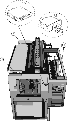
1 - motor interlock
2 - laser interlock
Figure 1 : Platesetter top view, interlock locations
Note: The motor interlock shown in the above figure shows the cheater used for the cassette interlock; the cheater used for the doors has a cap.
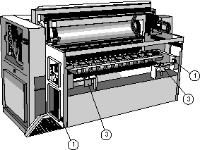
1 - motor interlock
3 - pins that lock the cassette
Figure 2: Platesetter front view, interlock locations
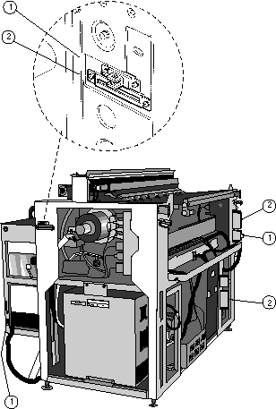
Figure 3: Platesetter side view, interlock locations
Note: The interlocks in the newer version machines have a new spring-loaded mechanism.
Optical Fibers
The laser energy is generated in the laser diodes, located in the L-box and conducted to the plotting head through optical fibers. Up to several hundred milliwatts of invisible laser radiation at a wavelength of 810-860 nanometers may be conducted in each fiber. This laser radiation is hazardous to the eye and skin.
|
|
The
service engineer must check and ensure that: |
|
|
If one of the many optical fibers is damaged or cut inside or outside the platesetter, and even when the doors are closed, invisible laser radiation of up to several hundred milliwatts at a wavelength of 810-860 nanometer may radiate outside the platesetter through the side door openings or through other openings. This laser radiation is hazardous to the eye and skin. Even brief exposure of the eye to this radiation or its reflection from shiny or matte objects can cause permanent degradation or permanent loss of eyesight ! |
Optical Head
The Optical fibers direct the laser radiation in the platesetter from the L-box to the plotting Optical head.
|
|
The optical head must never be activated if it is removed from its position on the guide beam. In addition, the optical head must never be activated when it is not in its proper position facing the drum, and with all the internal protective barriers assembled and all the doors closed. |
|
|
Never place any object in the path of the laser beam between the optical head and the drum. |
|
|
Up to several watts of invisible laser radiation at a wavelength of 810-860 nanometer may be present at the output of the plotting head. This laser radiation is hazardous to the eye and skin. Even brief exposure of the eye to this radiation or to its reflection from shiny or matte objects can cause permanent degradation or permanent loss of eyesight ! |
L-Box
The Laser diodes are located in the L-box on the left side of the platesetter. The platesetter must never be activated when the L-box is not in its proper location and the L-box door closed and properly fastened.
Before servicing the L-box, shut down the circuit breaker on the outer cover of the L-box.
|
|
Always use Static Electricity discharge before opening the L-box door or working with the Laser diodes. The Static Electricity discharge is located inside the L-box. |
|
|
After servicing or checking the L-box, make sure that all the laser fibers are properly connected and routed, and do not extend out of the L-box. When closing the L-box door, make sure you do not harm any of the fibers. |
|
|
If one of the many optical fibers is damaged or cut inside or outside the platesetter, and even when the doors are closed, invisible laser radiation of up to several hundred milliwatts at a wavelength of 810-860 nanometer may radiate outside the platesetter through the side door openings or through other openings. This laser radiation is hazardous to the eye and skin. Even brief exposure of the eye to this radiation or its reflection from shiny or matte objects can cause permanent degradation or permanent loss of eyesight ! |
Warning Labels
The following pages show the laser and other warning labels, and their locations.
Note: Numbers at the side of label indicate label position in the platesetter. Refer to location figures on following pages.
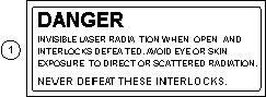
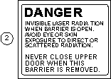
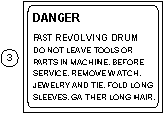
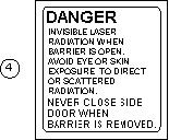
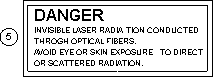
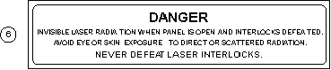
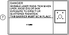
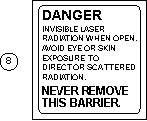

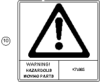
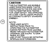
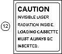

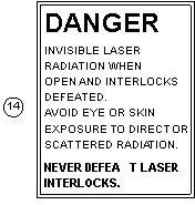
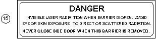
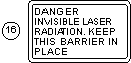
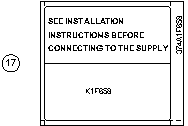
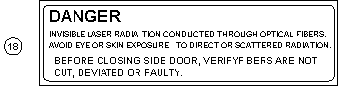
Make sure that all warning labels are in good order; renew warning labels if needed.
Note: When a language other than English is spoken, the service engineer should stick the translated labels (attached to the platesetter), in the relevant locations.
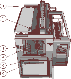
Figure 4: Top view, panels removed
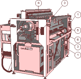
Figure 5: Right side view, panels removed
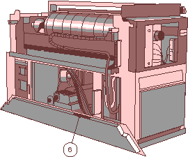
Figure 6: Back view, label on trapezoid panel
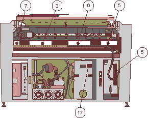
Figure 7: Back view, panels removed
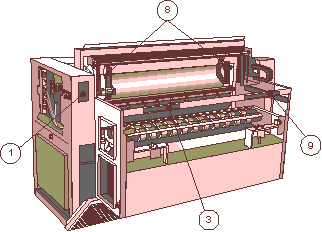
Figure 8: Front view, panels removed
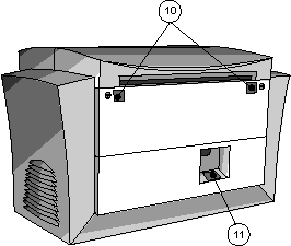
Figure 9: Back view with panels
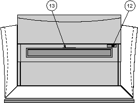
Figure 10: Front view with panels
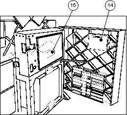
Figure 11: Right side door open
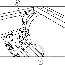
Figure 12: Upper rear door open, left side of drum
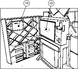
Figure 13: Left side door open
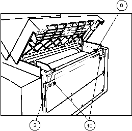
Figure 14: Upper rear door open
Copyright (c)1998 Scitex Corporation Ltd. All rights reserved. Certain names, logos, designs, titles, words or phrases on this page may constitute trademarks, servicemarks, or tradenames of CreoScitex Corporation Ltd. or other entities which may be registered in certain jurisdictions.
