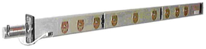
Remove the existing load gripper actuator assembly:
Tools required:
Small hex wrench with 5/32" bit:
Open wrench 11/16" or 17mm
Work bench/table
Procedure
Make sure that the gripper pins are not activated.
Disconnect the compressed air supply from the platesetter.
On the left side of the platesetter, use a small ratchet hex wrench to undo
the two screws located under the detector plate bracket. This will
release the lower gripper assembly from the bracket:
Do not loosen the screws holding the bracket to the frame.
Disconnect the lower actuator home and end position plugs:
On the right side of the platesetter, disconnect two compressed air hoses
connected to the air cylinder piston:
Loosen the nut securing the main pneumatic pressure valve (on the side of
air pressure manifold). Bend the pressure valve forwards. This will enable
you to slide the loading gripper actuator bar out of the platesetter:
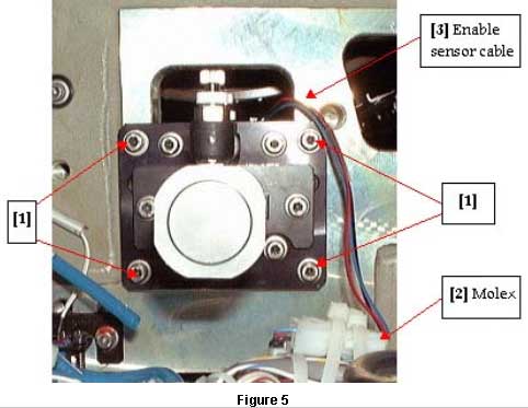
Disconnect the sensor cable at the Molex connector.
Remove the four screws holding the bracket in place:
Slowly slide out the lower gripper activator assembly. Note: When sliding out the gripper assembly,
ensure that it is held straight and that it is not obstructed in any way. Do not use force if there is an obstruction.
Place complete gripper assembly on worktable:
Reinstall the load gripper actuator assembly:
Prior to reinstalling the load gripper actuator assembly, make sure the
cavity for the gripper actuator assembly is clean and clear of any parts.
Slide the activator assembly into the optomech cavity until the flange holding
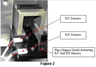
the EP/HP detectors stops it. Note: Check that the enable
detector is correctly connected, as shown in Figure 2.
Lift and slide the activator over the detector bracket taking care not to
damage the detectors (EP/HP).
Attach the air cylinder bracket to the optomech, by positioning it onto
the two locating pins. Insert and tighten the four screws, as shown in Figure
5.
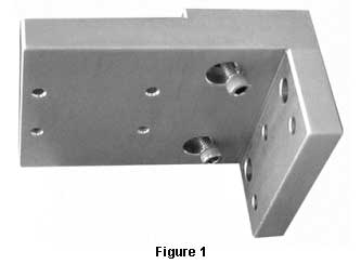
Tighten the two screws on the left hand side, as shown in Figure
1.
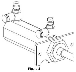
Connect the air tubes to the air cylinder, as shown in Figure
3. Make sure to connect the “in” and “out” tubes accordingly.
Reconnect the Molex connector of the sensor cable, as shown in Figure
2.
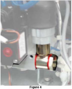
Position the main pneumatic pressure valve in its upright position and tighten
the bolt, as shown in Figure 4.
Connect the compressed air supply to the platesetter.
Test the load gripper actuator assembly:
From within Lotem Controller, open the drum motor.
Send the drum to the load gripper location position (approx. "
- 264") (Registry Loading System\setup "Load head gripper location").
After the drum reaches this position, activate the load gripper valve and
check that the actuator pins are in the middle of the head grippers groove.
Check that the flag (gripper guide) is activating the end position detector
and home position detector, as shown in Figure 1.
Perform a loading and exposure sequence to verify that the loading/unloading
processes are correctly working.