Home | Contact Us | Submit Troubleshooting Info | Search | Help


    Output | Software Solutions | Proofing | Color, Screening and Calibration | Scanning | Digital Photography | Consumables | POS


Replacing the Lower Roller Assembly

Prepared By: Dennis Kaliser
Date: January 2002

Disassemble

Tools

  1. Set Hex Keys (Imperial not metric)
  2. Pliers for the C Clip
  3. Work bench/table

Procedure

Ensure that Gripper actuators are not activated.

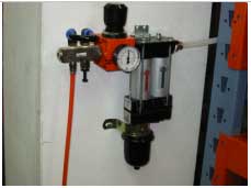
  1. Disconnect the compressed air supply to the machine.
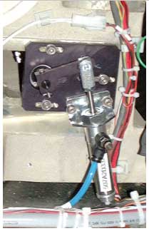
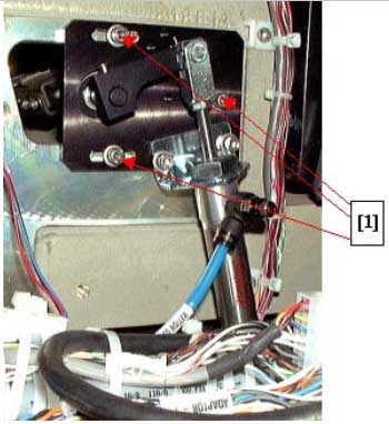
  1. Disconnect the air tube from the piston.
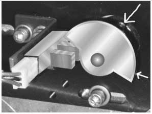
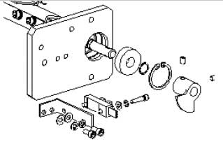
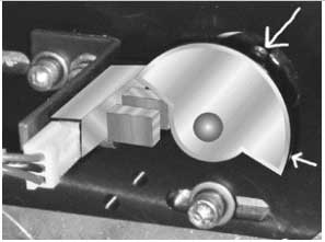
  1. Remove the HP flag. Note carefully the position of the flag before removal.Unscrew the two retaining set screws
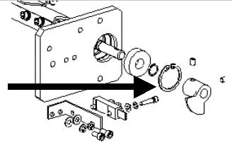
  1. Remove the C clip holding the shaft to the bearing on this sideNow go to the other sid
  1. Use a felt tipped marker to mark the position of the piston flange and the housing.
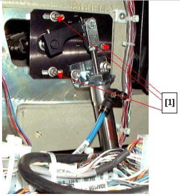
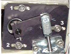
  2. Open and remove the 3 screws [1] holding the piston flange to the housing.
    NOTE: Steps 6 and 7 are only required if you intend to replace the piston or the flange with a new one. Otherwise, the piston and flange can be kept intact.
  3. Disassemble the piston in order to slide the roller assembly unit out smoothly.
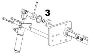
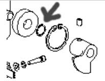
  1. Use pliers to extract the small securing C Clip [3] from the shaft on this side.
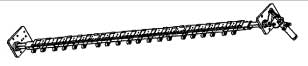
  1. Slide the roller assembly out of the bearing and then out of the Opto - Mec

Warning:

Be careful not to catch any rollers on the side of the housing block
while extracting the roller assembly.

Re-Assembling the Lower Roller Assembly

Note: Two people are needed to correctly insert the Lower Roller Assembly
into its housing.

  1. Slide the roller assembly into the Opto - Mech. Be careful not to catch any rollers on the sides
  1. Insert the flag axle on the end of the roller assembly and into the bearing at the other end of the housing.
  1. Position the piston flange against the Opto - Mech., Use the previously marked signs as a reference.

NOTE that in this picture, the piston was not separated from the flange.

  1. Assemble the small securing springNOTE: This step is only needed if the piston was separated from the flange.
  1. Insert three screws into the slotted holes and tighten. Do not apply Locktite to these screws.
  1. Attach the H.P. flag and tighten the two screws. The H.P. flag should have the flat edge facing down. Note the position of the flag in the illustration
  1. Attach the air hose to the piston. Connect the air pressure.

Testing

  1. Activate the piston to verify that the roller assembly operates correctly
  1. Load a plate and check for smooth operatio
 
  1. Expose a maximum image area 80% uniform tint. Check for any imaging problems (hot spots) that may result from uneven attachment to the drum.

    Copyright © 2005 Creo Inc. All rights reserved. Confidential. Back to top.