Home | Contact Us | Submit Troubleshooting Info | Search | Help


    Output | Software Solutions | Proofing | Color, Screening and Calibration | Scanning | Digital Photography | Consumables | POS


Upper Roller Assembly Replacement

Revised By: Dennis Kaliser
Date: January 2002

Disassemble

Tools

  1. Set of Hex Keys (Imperial not metric)
  2. Work bench/table

Procedure

Note: Refer to drawings
Ensure that Gripper actuators are not activated.

  1. Disconnect the supply of compressed air to the machine
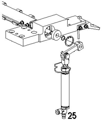
  2. Disconnect the air tube from the upper grippers cylinder piston (25)
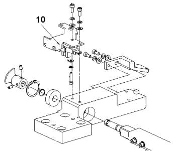
  1. Disconnect the cable from the HP roller sensor (10).
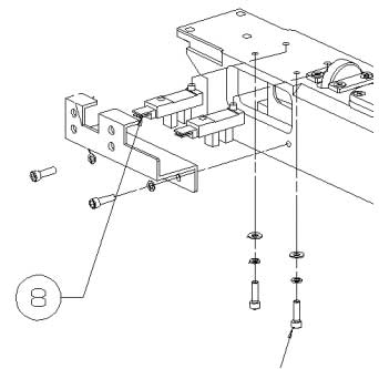
  1. Disconnect the cables from the EP and HP detectors of the gripper actuator (8)
  2. Disconnect Molex cables from Side to Side sensor.
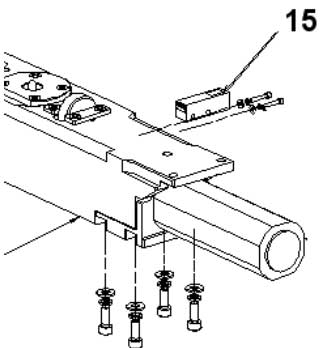
  1. Disconnect the enable sensor from upper gripper actuator (15).
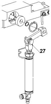
  1. Remove the cotter pin holding the bolt which connects the air piston arm to the roller assembly (27) and take out the bolt.
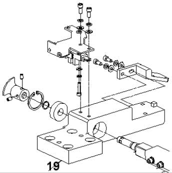
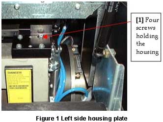
  1. Remove four screws from the right side roller housing plate (19)Do the same for the plate on the left side.
  2. Remove the entire assembly from guide pins. Place the complete assembly on a worktable.

Warning:

The Complete assembly must be held securely to ensure that it does not fall and damage the drum.


    Copyright © 2005 Creo Inc. All rights reserved. Confidential. Back to top.