Home | Contact Us | Submit Troubleshooting Info | Search | Help


    Output | Software Solutions | Proofing | Color, Screening and Calibration | Scanning | Digital Photography | Consumables | POS


Replacing the Drum Bearing Bolts due to Focus Variation along the Drum

Gabi Ra'anan
14-Feb-01

  1. Description of Problem
    The drum shaft is not properly secured to the chassis. Eventually, the drum moves out of place and exposure is out of focus. This usually happens on one side of the plate. Lines appear on one side of the plate. It was found out that some 20 machines manufactured around July 2000 had threads that were too short for the bolts, which secure the drum to the cassis. As a result, the bolts are tightened against the chassis but not the bearing housings. The drum shaft is not well secured.

  2. Solution
    Replace drum bearing bolts with shorter ones. Below is a step-by-step procedure that requires special tools that were supplied to each DU for this purpose.

  3. Tools and Parts

  4. Tool
    Supplied?
    Notes
    3-piece jig set
    Y
    Use to open drum motor nut (tool + 2 adaptors). Only one of the adaptors is used in this procedure. The other is used for removing the bearing on the encoder side.
    5/16" Allen bit
    Y
    For 3/8" driver Suitable for all motor, bearing housings, and carriage beam bolts.
    Torque wrench
    N
    350 kg/cm (or 300 lb./in.) to 1000 kg/cm (870 lb./in.)
    Ratchet wrench
    N
    With 3/8” driver
    Ratchet Extender
    Y
    3/8" X 5"
    Punch
    Y
    Use to knock the drum motor nut.
    Hammer
    N
     
    Film
    Y
    For easy separation of the drum rotor and stator.
    0.05 shim strip
    Y
     
    Dial indicator
    N
    For carriage beam parallelism.
    Spare drum motor nut
    Y
     
    3/8” x 1 ¾” bolts
    Y
    12 pieces
    3/8” spring washers
    Y
    12 pieces
    Blue Loctite 242
    Y
     
    Red Loctite 262
    Y
     
     
  5. Procedure

Important: Before touching the drum, look to see what has moved. Try moving the beam and tightening its bolts to 350 kg/cm (300 lb./in) torque. If the bolts are loose, it indicates that the carriage beam has shifted. 
  1. Remove the five (5) bolts on the encoder side.
  2. Replace them with the shorter bolts supplied in the kit (3/8"x 1 ¾” + spring washer).
  3. Apply Blue Loctite and torque bolts to 350 kg/cm (300 lb./in).
  4. Push the shaft forward while tightening it to make sure the bearing housing is attached to the main structure.
  5. Remove the drum motor in the following steps:

    1. Disconnect the motor connectors.
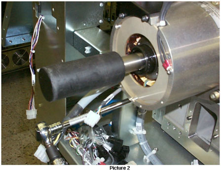
    2. Remove the vacuum swivel from the shaft (see Picture 1).
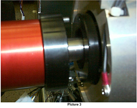
    3. Use the punch and tap it with a hammer to remove the Loctite that secures the drum motor nut (see Picture 2).
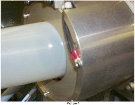
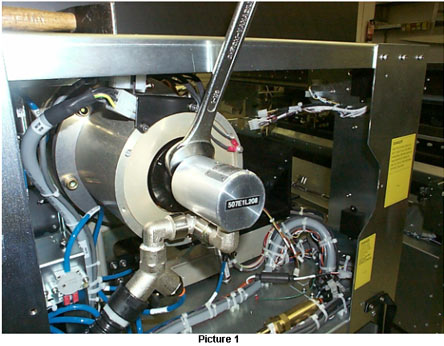
    4. Use the jig and adaptor together with the ratchet wrench to open the drum motor nut (see Pictures 3 and 4).
    5. Insert the supplied film around the motor rotor to prevent contact between stator and rotor magnets. Most of film should fit in (see Picture 5).
    6. Remove the bolts that secure the drum motor.

  6. Remove the five (5) bolts from the bearing housing.
  7. Replace them with the shorter bolts supplied in the kit (3/8"x 1 ¾” + spring washer).
  8. Apply Blue Loctite and tighten the torque bolts to 350 kg/cm (300 lb./in).
  9. Push the shaft forward while tightening it to make sure the bearing housing is attached to the main structure.
  10. Reinstall the drum motor.
  11. Apply Red Loctite to the bolts and tighten the torque bolts to 350 kg/cm (300 lb./in).
  12. Tighten the rotor nut using the jig to a torque of 1000 kg/cm (870 lb./in.).
  13. Apply Red Loctite.
  14. Reconnect the vacuum swivel, applying Teflon tape to prevent vacuum leakage.
  15. Reconnect all the motor connectors.
  16. Adjust the carriage beam parallel to the drum using a dial indicator.
  17. Perform the focus and resolution adjustments.


    Copyright © 2005 Creo Inc. All rights reserved. Confidential. Back to top.