

Home | Contact Us | Submit Troubleshooting Info | Search | Help
Output | Software Solutions | Proofing | Color, Screening and Calibration | Scanning | Digital Photography | Consumables | POS
Home | Contact Us | Submit Troubleshooting Info | Search | Help
Output | Software Solutions | Proofing | Color, Screening and Calibration | Scanning | Digital Photography | Consumables | POS
This procedure requires two people.
One person needs to move the drum and hold it in place while the other operates
the GUI.
The result of this procedure will be to modify two values in the registry.
| Manually move the balance weights to the stoppers on both sides of the drum. |
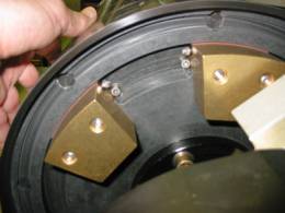 |
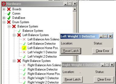
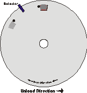
| Position the drum by hand so that the balance detector is centered
between the stoppers. Hold the drum in place |
 |
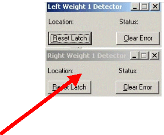 While holding the drum in place, press Clear Error and then Reset Latch
for both detectors
Make sure that the status is now off for both weights.
| Open the Drum Motor window. | 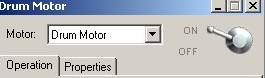 |
| Do "Drum Init" from the loading system menu. Cut the drum power allowing the drum to fall. | 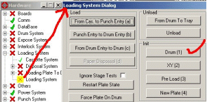 |
| Manually extend the weight locating arm on one side. Be sure that the extended arm is below the lower weight. Keep the arm extended and gently rotate the drum further until the weight rests against the extended arm. | 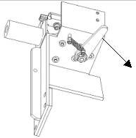 |
| From the drum motor window, record the drum position. Allow the locating arm to retract and let go of the drum. | 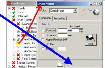 |
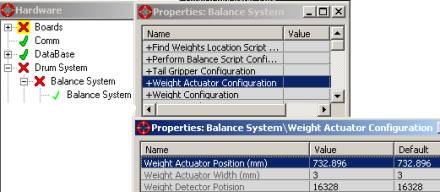
The adjustment procedure is now complete. To test the results, double click
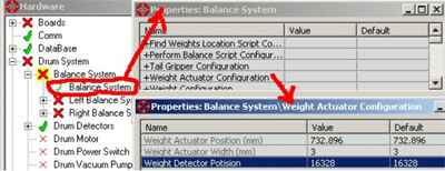
on "Hardware/Drum System/Balance System/Balance System". Click on
"Perform Balance" and check the location of the weights.
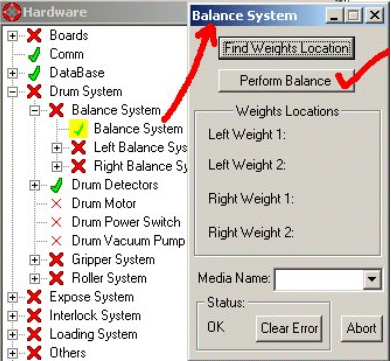
Weight locations should conform to FSB 98-0003 as follows
PLATE Thickness= 0.3 mm
| Plate length Drum Circumference | Plate width Drum axis | Weight location (degrees) | Weight location (degrees) |
|---|---|---|---|
| 630 | 720 | 70 | 17 |
| 636 | 968 | 72 | 15 |
| 708 | 975 | 100 | 40 |
| 770 | 1030 | 125 | 62 |
| 784 | 1030 | 130 | 68 |
| 790 | 1030 | 132.5 | 70 |
| 800 | 1030 | 136 | 74 |
Change the plate in the cassette and Re-Do "Perform Balance" with each size plate you are using.