Procedure |
|
This procedure includes the following sections:
Preparation
- From the application, open both the front and right doors.
- Load Lotem 800 PC software version 3.61.02, according to the Release
Notes.
- Close the application; then perform a complete machine shutdown.
- Open the E-box and locate the MCF board (upper board).
- Disconnect both the Drum Encoder and Edge Detection
connectors, as shown in Figure 1.
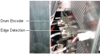
Figure 1
- Remove the existing MCF board and insert the new MCF 2 board,
as shown in Figure 2.
Note: If the new board is in a different revision level
(A or C), replace the MCF Xilinx files according to the MCF
Board Replacement procedure.
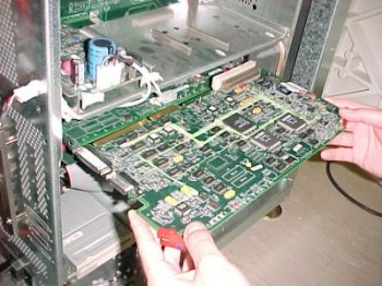
Figure 2
- Reconnect the Drum Encoder and Edge Detection connectors that you
removed in step 5. Make sure to tighten the screws
of both connectors.
- Close the E-box.
Side panel Distribution box connections
- Remove the lower back panel of the Lotem by releasing the four screws.
- Disconnect the Interlock Molex connector on
the side panel of the Distribution box, as shown in Figure 3.
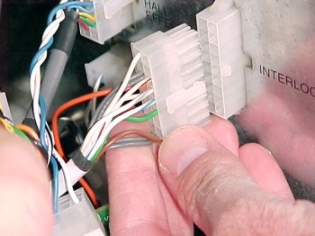
Figure 3
- Disconnect Molex connectors J1 (Drum Motor Command)
and J2 (Hall Effect) from the side panel of the Distribution box, as
shown in Figure 4.
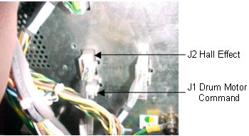
Figure 4
- Insert the orange wire from Cable No. 3 into slot 6 of the Interlock
connector that you disconnected in step 2, as
shown in Figure 5.
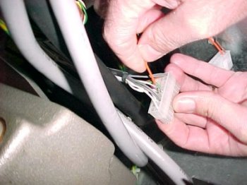
Figure 5
- Reconnect the remaining two cables to the Inhibit Adaptor Board Assembly,
as shown in Figure 6.
Note: Each connector/connection is custom-fitted.
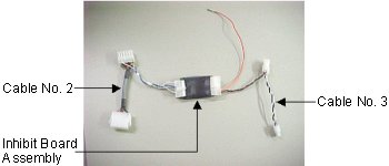
Figure 6
- Connect one side of Hall Effect Cable No. 2 to the original Hall
Effect J2 connector (that you disconnected in step 3),
as shown in Figure 7, and the other side of Hall Effect Cable No.
2 to the Hall Effect Molex J2 connector in the Distribution box, as
shown in Figure 8.
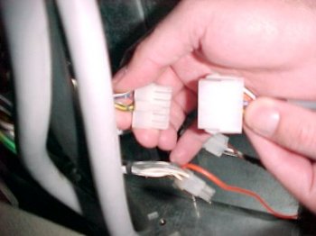
Figure 7
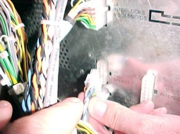
Figure 8
- Reconnect one side of Cable No. 3 to Connector J1 (Drum Motor Command)
that you disconnected in step 3, as shown in
Figure 9, and the other side of Cable No. 3 to Connector J1 (Drum
Motor Command) on the side panel of the Distribution box.
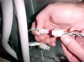
Figure 9
- Using a flat screwdriver, push the Interlock Molex (female) connector
into the Distribution box, as shown in Figure 10.
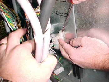
Figure 10
Internal Distribution box connections
- Open the Distribution box.
- Disconnect the Interlock Molex (male) connector from the Laser Interlock
board, as shown in Figure 11.
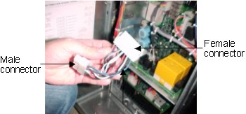
Figure 11
- Insert the orange wire pin of Cable No. 1 (shown in Figure 12) into
slot No. 6 of the Interlock Molex (female) connector that was previously
connected to the side panel of the Distribution box, as shown in Figure 13.
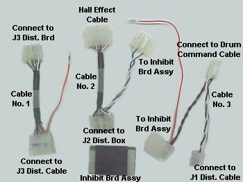
Figure 12
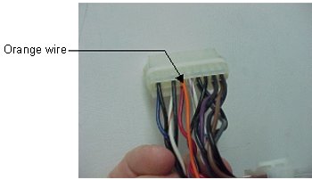
Figure 13
- Disconnect Connector J3 from the Distribution
board, as shown in Figure 14.
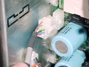
Figure 14
- Reconnect the Interlock Molex connector to the Interlock board, as
shown in Figure 15.
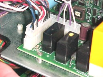
Figure 15
- Return the Interlock Molex (female) connector back to its place in
the side panel of the Distribution box.
Note: This connector was removed together with its
male counterpart, as shown in Figure 11.
- Reconnect Connector J3 (that you disconnected from the Distribution
board in step 4) to Cable No. 1, as shown in
Figure 16.
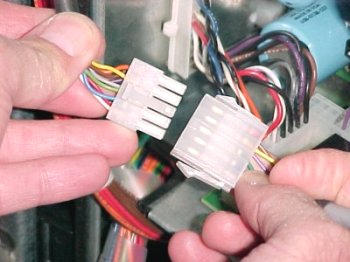
Figure 16
- Insert the remaining Molex connector (Cable No. 1) into Connector
J3 on the Distribution board, as shown in Figure 17.
Figure 17
- Reconnect the Interlock connector on the side panel of the Distribution
box, as shown in Figure 18.
Figure 18
- Close the Distribution box.
- Replace the rear back panel.
- Close the right door.
- Close the front door.
- Power on the Lotem.
- Run the application.
- Ensure that the Lotem is in Ready mode.
|

