Home | Contact Us | Submit Troubleshooting Info | Search | Help
Output | Software Solutions | Proofing | Color, Screening and Calibration | Scanning | Digital Photography | Consumables | POS
Home | Contact Us | Submit Troubleshooting Info | Search | Help
Output | Software Solutions | Proofing | Color, Screening and Calibration | Scanning | Digital Photography | Consumables | POS
|
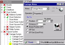
Send the carriage to the end position on the left side. (Hardware/Expose System/Carriage System/Carriage Motor) |
 |
Turn the machine power off from the main power switch.
|
Open the top rear cover. Remove the upper rear panel. Remove the unload tray. Insert cheaters in place of the removed cover and panel. |
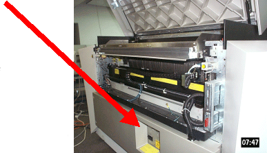 |
Remove the right Local Board close to the carriage motor (Right Side)
If the Lotem is a local 2 machine, remove the local board on the left side as
well.
|
Go to the left side of the machine. |
 |
|
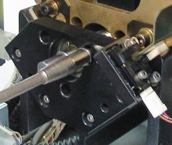
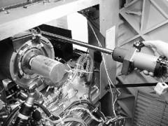
You must go through the three holes in the bearing housing to reach the coupling screws. |
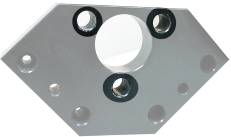 Bearing Housing |
|
If you can't reach the three screws through the bearing housing, you can first remove the standoff screws mounted on the carriage which keep the carriage from touching the bearing housing. |
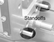 |
|
Note: If your extender is not long enough or thin enough to reach through the bearing housing to the three coupling screws (even with standoffs removed), you may need to remove the bearing housing. |
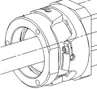 Location of three screws on the coupling |
Go to the right side (Stepper Motor side) of the machine.
Disconnect the Coarse and Fine home position detectors.
Disconnect the stepper motor.
|
Remove the four screws holding the bracket (right bearing housing) to the V block. Be careful to remove the ground wire on one of these screws as well as the Molex connector mounted on another of the four screws. Do not remove the screws holding the stepper motor to the bracket. |
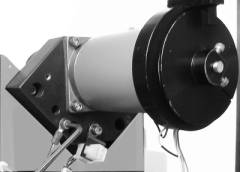 |
|
Pull out the lead screw with motor attached. Be careful not to damage the leadscrew or leadscrew threads while doing this. |
 |
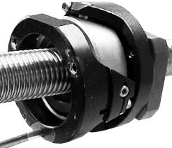
A Leadscrew Coupling Locator jig (PN 291A3L006) is required to align the mounting screws to the gimbaled coupling bearing.
Before starting the reassembly, use the opportunity to thoroughly clean the V block (carriage beam), the carriage and brackets.
|
Insert the Leadscrew Coupling Locator jig into the tap opposite the flat edge of the coupling. |
 |
|
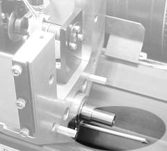
Insert the lead screw with jig carefully through the carriage block. The jig should go through the bottom of the three holes in the bearing housing. |
 |
Insert the top two of three screws that hold the coupling to the V block.
Do not tighten these screws yet.
Remove the jig and insert the third screw in its place.
Now tighten all three screws.
Go to the right side of the machine and reattach the bearing housing and stepper motor. (4 screws).
Reconnect the home and fine home position detectors.
Reconnect the Molex bracket and ground wire on the stepper motor.
Replace the local board on this side.
Return to the Left side
Replace the oil brackets
Replace the standoffs and local board if previously removed.
Power on the machine and test to see that the carriage assembly works by:
Sending the motor to the H.P. with the GUI.
Check the position of the fine detector. The slit in the detector wheel should
be opposite the detector.