
Home | Contact Us | Submit Troubleshooting Info | Search | Help


    Output | Software Solutions | Proofing | Color, Screening and Calibration | Scanning | Digital Photography | Consumables | POS


Front Door Interlock Adjustments

General

The following is the improved Front door interlocks adjustment procedure that we are implementing today at the assembly line (10/12/98).

There are two standard shims that we are using for the interlock adjustments (Laser and Motor Interlock).
You will find two kind of standard shims under the Interlock Units.

The P/N of the shims are:

  1. 281A8L635
  2. 281A8L636.

For your convenience the shims are incorporated into the spare parts kit on site.
All the machines with S/N higher then 98500175 have already ben adjusted on the assembly line with the attached procedure.
The following procedure needs to be implement only if you are facing problems with the front door interlock adjustments.
This procedure is relevant for the Q3 /Q4 machines.(the 70 machines batch)

Front Door Interlocks Adjustments Procedure

  1. Open the front door
  2. Remove all existing shims (under the interlocks box) from the Laser & Motor interlocks
  3. From the PC, open the window of the laser front door and motor front door.
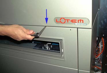
  4. Close the front door and check the distance from the front door to the front lower cover. The distance should be 3 mm on both side of the front door. (use a filler gauge), See picture 1.
  5. If the distance is not 3 mm adjust the solenoid door locker. There are 4 screws that you need to open in order to adjust the front door locker position.
  6. When complete, check that the distance is 3 mm.
  7. Close the front door and check for the following status:
    • If the status of the front door is off this indicates that the door is closed, go to step 11.
    • If the status of the front door is on this indicate that the door is open. Go to step 8.
  8. Insert shims of 4 mm under the front door interlocks (motor, Laser) and then go to step 7.
  9. Close the front door slowly and find the point where the status of the front door changes from off to on.
    From the point that you have now found measure the distance to the front lower cover. Define this distance as B.

  10. Note:
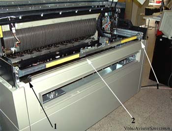
    For your convenience connect a thin rubber band between the right door solenoid to the left door solenoid, in order to eliminate activation of the solenoids when implementing the above procedure. See picture 2

  11. Insert shims under the front door interlocks, where the thickness of the shims is calculated according to the following calculation: 3-B+2 mm.
    Go to step 7.
  12. Open the front door and find the point where the front door status window changes from off to on. Measure this distance from the change point to the lower front cover.
    Define that point as A. (See 9 Note)
  13.  
    • If A-3 < 2 you need to add shims with the thickness of 2-A+3 mm, round the result to upper range. (for example if the reasult from the calculation is 2.3 mm the final thickness of the shims should bee 3 mm. Go to 7.
    • If A-3 >2 (or equal) the procedure is completed.

Picture 1

Picture 2
1 – Front door solenoid
2 – Rubber band that need to connect in order to eliminate the door solenoids
    Copyright © 2005 Creo Inc. All rights reserved. Confidential. Back to top.