Procedure |
|
To replace the unload rollers, do the following:
- From the Lotem Controller, open the platesetter's rear door.
- Disconnect the air supply leading to the platesetter.
- Remove the rear upper panel.
- Remove the platesetter's unloading tray. Take care when disconneting
the piston hose and the connectors. Place the tray on a work table.
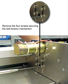
- Release the belt tension mechanism by removing
the four screws that hold it in place:
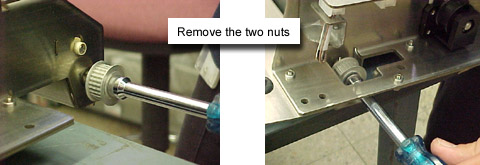
- Remove the two nuts securing the two sprocket wheels:
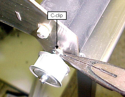
- Extract the two C-clips from behind each of the two sprocket wheels:
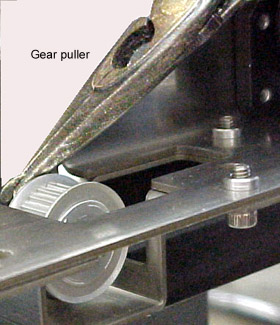
- Extract the sprocket wheels from the external shaft. If necessary,
use a gear puller:
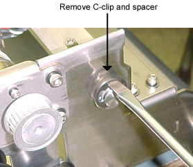
- Using a flat screwdriver, remove the C-clips and spacer from the
GTO arm:
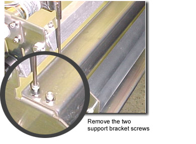
- Remove the two screws on the support bracket:
- Remove the screws connecting the vertical support
from the horizontal support:
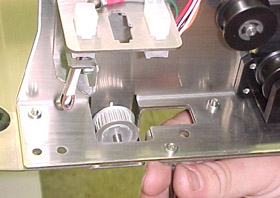
- Pull out the vertical support together with the inner roller and then
extract the sprocket wheel:
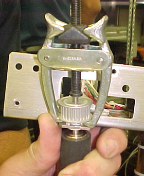
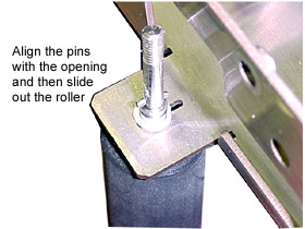
- Align the pins with the opening on the bracket and then slide out
the roller:
- Remove the old bushings from the rollers.
- Install the new rollers on the unloading tray:
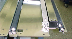
- Re-install (but do not secure) the inner sprocket onto the inner roller.
- Re-install the support bracket.
- Using Loctite 242, re-insert the screws you removed in steps 10
and 11.
- Re-install (but do not secure) the external sprocket.
- Using Loctite 242, secure each of the inner and external sprockets
with a locking washer and nuts.
- Re-install the belt:
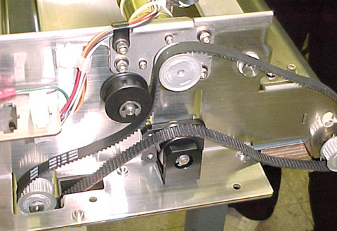
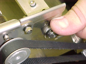
- Apply Loctite 242 to the ends of the belt tension mechanism screws
and securely tighten them.
- Re-install the two C-clips onto the rollers:
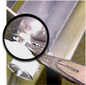
- Re-install the C-clips onto the GTO arm:
- Lift up the tension wheel and place the tension jig (p/n 518-00321A)
underneath the wheel:
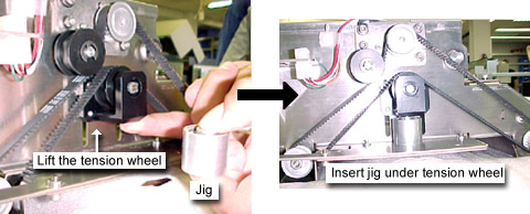
The jig supports the tension wheel and the jig's spring will set
the belt tension to approximately 1.5 Kg.
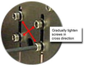
- Replace the four belt tension mechanism screws you removed in step
5. Gradually tighten each screw, working in a cross direction:
- Remove the jig.
- Re-install the the unloading tray into the platesetter as follows:
- Reconnect all the screws, the air hose and the electrical connectors.
- Reconnect the air supply, making sure that the GTO arm is in an
upright position.
- Replace the platesetter's rear panels and then close the rear
door.
|

