Home | Contact Us | Submit Troubleshooting Info | Search | Help


    Output | Software Solutions | Proofing | Color, Screening and Calibration | Scanning | Digital Photography | Consumables | POS


Plate Centering Adjustment

Re-edited by: Dennis Kaliser
Date: 11 Oct 01
The previous procedure "Plate Centering Adjustments" called for the use of a pair of centering jigs. Since these jigs may not be available in the field, the following procedure describes how to adjust the plate centering system without jigs.
This document also revises the subsequent "centering system factor parameter adjustment procedure".


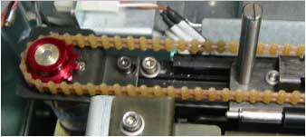
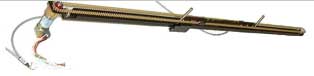
  1. Mount the plate-centering system on the
    chassis in front of the punch bar assembly.
    The mounting holes in the centering assembly
    are slotted allowing for some adjustment left or right.
  1. Connect the centering cables and the motor cable.
  1. Insert the four retaining screws that connect the centering assembly to the chassis.
  2. Position the screws in the approximate center of the slotted holes.
    Tighten the screws.
  3. Bring the centering pins to their maximum open position by hand.
  4. Load a plate onto the drum using the GUI.

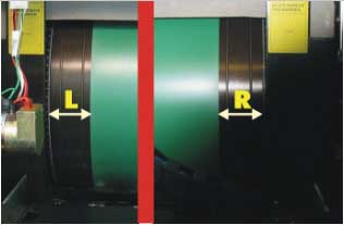
  1. Measure the distance from the edge of the plate to the edge of the drum on each side of the plate (in the lead screw direction).
  1. Subtract the lesser distance from the greater distance and divide by two (see example below). Then loosen the mounting screws and move the centering assembly by this factor towards the side with the greater distance. Tighten the screws

    Example: Plate to drum edge left side measures 19mm.
    Plate to drum edge right side measures 23mm
    Difference = 4 mm divided by 2 = 2mm
    Move the centering assembly 2 mm to the right.

  2. Repeat steps 6 & 7. If the difference between sides exceeds .5mm, repeat step 8.
    Ensure that the difference between the two sides does not exceed 0.5mm.
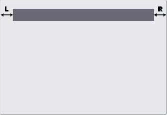
  3. Test the accuracy of the adjustment by exposing a plate with a flat tint spanning about 85% of the plate width across the drum. The image dimension around the drum needs only to be about 10mm. Measure the distances from the image edge to the plate edge on both sides. The difference should not exceed 0.5mm.

  4. Following this procedure, you need to fine tune the centering motor factors in the registry.
  5. Use the following procedure to do this.

Centering System Factors
Parameter adjustment in the Registry

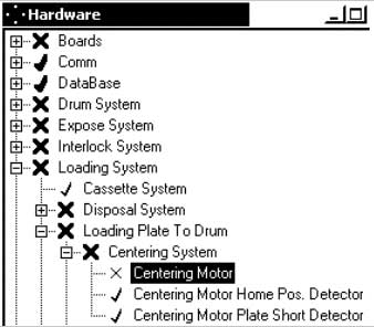
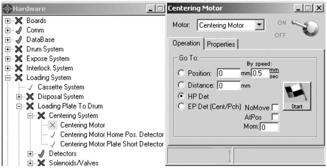
  1. From the Lotem 800 GUI Click to open Hardware>Loading System > Centering System >Centering Motor

Select the Centering Motor and click the right mouse button to reach Pos factor and Virtual Hp App Value:
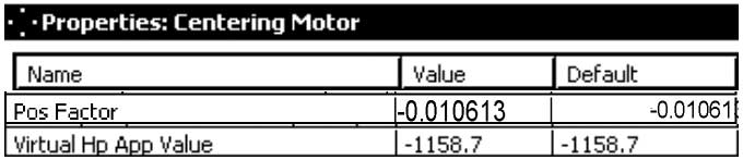
  1. Make a note the original Pos Factor .Be sure to include the + or - sign
    Change the Pos Factor to 1
    Change the Virtual H.P APP Value to 0
    Click Apply
  2. Place a plate of known size manually in the centering system.
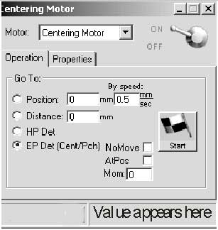
  3. Double left click on …centering system/centering motor and then click on HP Det
    Click start.
  1. Click on EP Det (Cent/Pch) and then Start. The centering system moves to the centering position (EP). When the center motor reaches this position, a value will appear in the lower right block of the Centering Motor window. Write this value down.
  1. Send the pins back to home position (HP Det) and Repeat the process 5 times.
    Note: While "Centering" make sure that the plate is straight along both axes.
  2. Calculate the average value of the 5 results from this position.
  3. Enter the result into the following formula :
    Virtual H.P APP =
    ( Average value from tests ) * (original Pos Factor) - ( Plate Size )
  4. Enter this value into
    Loading System > Centering System > Centering Motor > Virtual H.P. APP Value.
  5. Change the Pos Factor from 1 back to its original value.
  6. Check a number of plate sizes, by performing centering, Verify that the value
    received in the Centering Motor window matches the width of the plate.

    Copyright © 2005 Creo Inc. All rights reserved. Confidential. Back to top.