Home | Contact Us | Submit Troubleshooting Info | Search | Help


    Output | Software Solutions | Proofing | Color, Screening and Calibration | Scanning | Digital Photography | Consumables | POS


Installing the 0.15 mm Plate Support Kit

Gabi Ra'anan
14-Jan-01

Abstract:

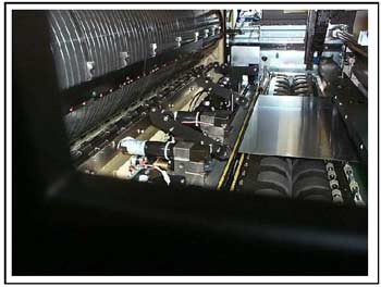
This kit was created to enable loading of small plates with thickness of 0.15mm. The main problem when loading such a thin plate is a significant deflection of the front edge of the plate that makes the loading impossible. New rotating plate supports prevent the plate front edge from colliding with the punches, by pneumatically raising the plate edge above the punches.

Prerequisites

Installation Procedure

Software Changes
  1. Open front and rear doors, remove back upper panel.
  2. Replace loading system scripts with the new set from floppy disk shipped with the kit:
  3. Start Windows Explorer and open Lotem/Lotem800/scripts/Loading System.
  4. Create a new folder, name it Loading Backup and copy Loading System to the backup file.
  5. Copy all files from the floppy to Loading System. Remove the floppy disk.
  6. Restart the application.

Hardware Changes

  1. Shut air pressure supply off.
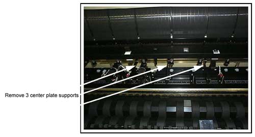
  2. Remove three center plate supports (507A2D414) from punch beam.
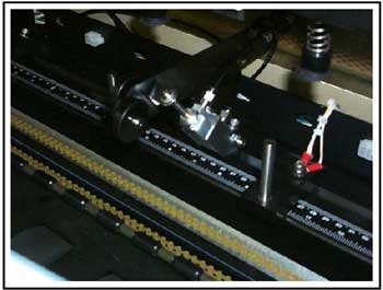
  3. Install the new rotating plate supports (507B3D614). The distance between them should be as wide as possible (according to the min. plate size and punch system configuration)- as long as the plate does not deflect down in its middle
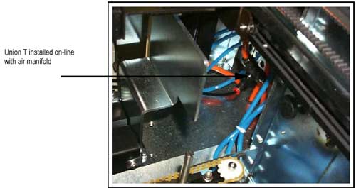
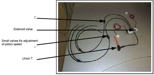
  4. Disconnect orange air tube from the air manifold (labeled "Manifold Pressureld") and install union T inline.
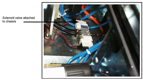
  5. Attach solenoid (347B55600) to the chassis with double-sided tape (There is a free space on the right side of the punch beam).
  6. Connect black tubes to rotating supports pistons. Route the tubes behind the punch beam and secure with tie-wraps while ensuring that: A.The supports are free to rotate up and down. B.The tubes do not stand in the way of the loading system when it approaches the drum.
  7. Insert solenoid plugs to punch inlets #9 and #10. If these inlets are occupied by punches- please call Gabi/Pavel for special instructions.
  8. Turn the air pressure valve on and set a normal pressure (6 bars).
  9. Enable the chosen punches in the Registry:
    Others/Lotem 800/IO objects/ {chosen punch motors (see paragraph 10)} -> i>openlp = 1, i,hp detector ie= none.
  10. Open the punches dialog boxes and switch them on/off in to check connections.
  11. Adjust little air valves to get smooth motion of the pistons.
  12. Open rear door and rear upper panel.
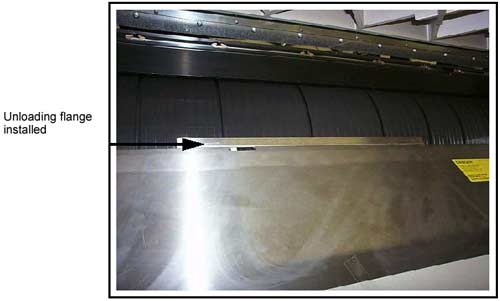
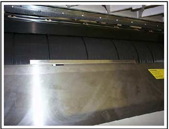
  13. Assemble unload flange (294A2S137) on the unload surface.
  14. Install the rear upper panel.

Working with new plates

  1. Define new plate sizes in the Registry.
  2. Test the plate loading. Test should include at least 10 small plates and 10 different plate sizes the customer uses.
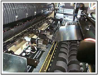
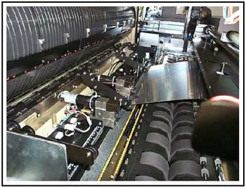
  3. Loading Sequence I-Plate lifted

    Loading sequence II-Supports lowered
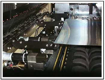
    Loading Sequence III-Supports raised

  4. If plates get jammed at the punch guides, replace the guides with the ones supplied with the kit (P/N 290A2T777 or 290A2T778 for single or double punch).
  5. Change the following parameters if necessary:
  6. Loading system/ Load plate/l6Min plate height for air during Y Upli and ln Min Plate height for air during X Movingl6 (If you need to prevent air stream from Blowing the paper into the cassette and the plate width for example is 510,
  7. Set parameter to 511, so when a plate 510 wide or smaller is loaded- the air will be switched off); - Others/Lotem 800/machine/lsMin media width sizell and inMin media height sizel.
  8. (You might need to set values smaller from the default, depending on the minimum plate size in use).

  9. Loading system/load plate/paper disposal/lroperate vacuum during paper disposalll ŒDisable suction if the plate is lifted together with the plate.

  10. Note the new parameters:


    Copyright © 2005 Creo Inc. All rights reserved. Confidential. Back to top.