Background
|
|
The front door of the Lotem should open and close easily. There
should also be 3 millimeters of clearance between the bottom of
the door and the top of the upper front panel. If the door does not
open easily, or if there is too little clearance, the front door
locking assemblies must be adjusted.
|
Procedure
|
|
- Open the front door.
- Remove the right and left upper front side panels.
- Remove the upper front panel.
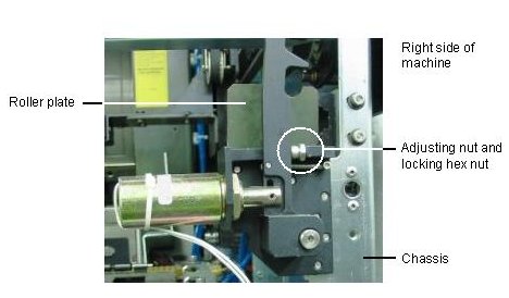
- Adjust the arm of right and the left locking assembly:
- Open the adjusting nut (shown below) by turning it
360° twice—it should move toward the center of
the machine.
- Close the locking hex nut (shown below) by turning
it—it should move toward the outside of the
machine.
- Adjust the position of the right and
left roller plate:
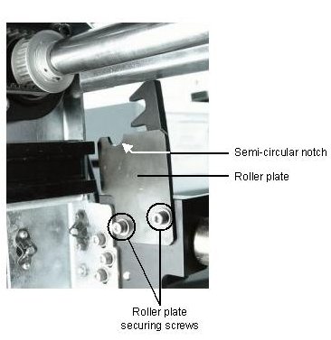
- From inside the chassis, loosen the two plate
securing screws (shown below from inside the
machine) and press the plate downward as far as it
will go.
Note: Notice the semi-circular
notch on the top of the roller plate.
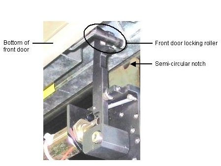
- Close the front door and, using a flashlight,
inspect the area of the semi-circular notch on the
plate.
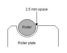
- Move the plate until the front door locking roller
(shown in the picture below) is centered in the
semi-circular notch and 2.5 mm away from its
edges, as shown in the following drawing.
- Hold the plate in place and tighten the two plate
securing screws.
- Place the upper front panel back on the
Lotem. Do not secure it in place.
- Close the front door and, using a feeler gauge, verify that
there is at least 3 mm clearance between the bottom of
the front door and the top of the upper front panel at any
given point. If there is not enough clearance, adjust the
position of the right and left locking assemblies:
- Open the front door and remove
the upper front panel.
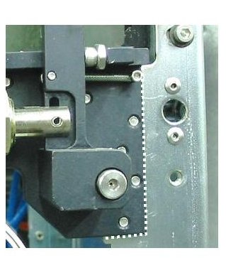
- Use a pen or pencil to trace
the shape of the locking assembly on the chassis (as
represented by the dotted line in the picture
below).
Note: Do not use an erasable
marker.
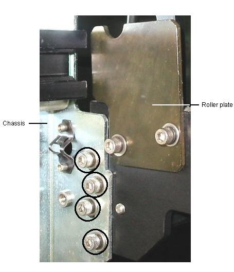
- From inside the chassis, loosen the four locking
assembly securing screws (circled in the picture
below)—do not remove them.
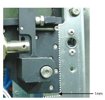
- Raise the locking assembly 1 mm.
Tip: Use the line you drew in step b
as a reference—the bottom of the assembly should
be 1 mm above the line you drew, and the side
of the assembly should be aligned to it, as shown
below.
- From inside the chassis, tighten the four locking
assembly securing screws.
- Repeat steps a through e on
the other side.
- Repeat steps 6 and 7.
If the door does still not close properly, check the
roller plate to verify whether the newer version,
which has a larger semi-circular notch, is installed
(shown below).
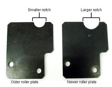
If the newer plate is not installed, , install the newer one, and repeat steps 5
through 7.
- Secure the upper front panel in place using the four screws
and lock washers that you previously removed.
- Replace the right and left upper front side panels and close
the front door.
- From the PC controller, open the front door and verify that
it opens properly.
|

