

Home | Contact Us | Submit Troubleshooting Info | Search | Help
Output | Software Solutions | Proofing | Color, Screening and Calibration | Scanning | Digital Photography | Consumables | POS
Home | Contact Us | Submit Troubleshooting Info | Search | Help
Output | Software Solutions | Proofing | Color, Screening and Calibration | Scanning | Digital Photography | Consumables | POS
The installation of punches covers the procedure for installing or repositioning customer punches.
|
The machine is supplied with a spiral punch, 2 Stop (short) Pins and 4 Plate Supports with guide wheels. The 2 Stop (short) Pins ensure that the front plate is positioned parallel to the drum before punching. The 4 Support guide wheels guide the plate onto the drum after it has been punched.Both the Plate Supports and the Stop Pins can be moved where necessary. |
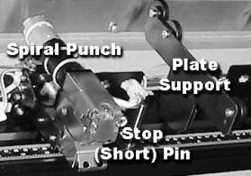 |
Ten punches including the spiral punch can be installed on the machine. The
distance between punches is determined by the punch system on the press.
|
1. Position the punch on the punch bar and fasten it to the closest T nut in the T-slot in the punch bar. |
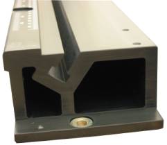 |
| 2. Note: 9 T nuts are supplied in the T slot with newer machines. The spiral punch has already been installed. The T nuts are not in any fixed position. | 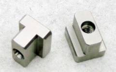 |
| 3. Tighten the screw connecting the punch to the T nut. Continue tightening the screw until the punch is secured firmly in place on the bar. Note: Older Lotems used a diamond nut which was tricky to thread in the bar. |
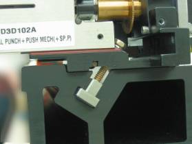 |
Normally, a template is supplied by the sales support specialist showing you exactly where to position the punches. If not, you may be told only the distance between punches which are to be centered on the plate. See the following example.
Example calculation:
Install two punches where the distance between punch centers is 780 mm. The two punches in this case have been specified to be equidistant from center. All measurements on the drum are referenced from center.
The distance from drum center to punch center for each punch is 390mm (780/2).
The punch housing is 30mm wide. The distance from drum center line to the near edge of the punch housing is then the desired distance minus 15mm. In this example, the near edge of both punches should be positioned 375 mm from the 0 centerline. 390-15 = 375.
|
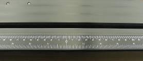
4. Use the ruler on the punch bar for all measurements. |
 |
| 5. Note: The width of a double punch housing is 50mm. The distance from center to near end of the punch would then be desired distance minus 25 mm. | 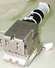 |
| 6. If a Stop Pin or Plate Support interferes with the punch position, it can be moved. Open the retaining screw and move it to the left or the right of the punch. | 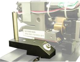 |
| 7. Connect the motor cable and the earth cable from each punch to the connector attached to the punch bar. | 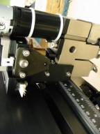 |
After all the punches have been installed, load a plate using the automatic loading system:
Notes:
Punch motors in some DU's inventory are missing the pin for the shaft. Pins
need to be ordered separately. Part number 507A3E655 provides for you to get
both the punch motor and the pin, which have already been fastened with Loctite.
(Details see: TIC | Technical Notes | Memos | Punch Motor + Pin Assy 02-Apr-01)
|
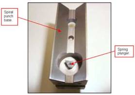
A spring plunger has been placed inside the spiral punch base (P/N: 507C3D101A) to remove slugs away from the plate. This prevents slugs from reaching the drum and causing registration problems. (See: TIC | Technical Notes | Memos | Spiral Punch + Spring Pin Assy 02-Apr-01) |
 |