

Home | Contact Us | Submit Troubleshooting Info | Search | Help
Output | Software Solutions | Proofing | Color, Screening and Calibration | Scanning | Digital Photography | Consumables | POS
Home | Contact Us | Submit Troubleshooting Info | Search | Help
Output | Software Solutions | Proofing | Color, Screening and Calibration | Scanning | Digital Photography | Consumables | POS
Revised By: Dennis Kaliser
Date: March 2002
The depth of spiral punch must be adjusted so that images are exposed square to the plate gripper edge.
Unless specified differently, image positioning must also be accurate to the plate center in the across the drum cylinder direction.
Adjustment for both of these requirements is done by entering values in the Spiral Punch Calibration window of the GUI.
Right click on the Punch Spiral Motor
Utilities/Hardware/Punch System/Spiral Punch System/Punch Spiral Motor
Two windows will open.
The properties window and the Spiral Punch Calibration window.
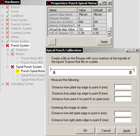
Make sure the Virtual HP App Value equals the default value of =700.
Click Apply in the properties window.
Keep all the windows open.
|
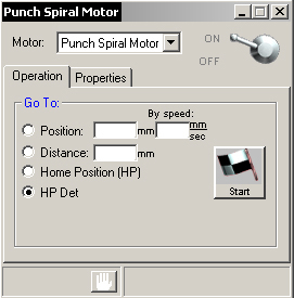
Left click on the Punch Spiral MotorUtilities/Hardware/Punch System/Spiral Punch System/Punch Spiral Motor Send the motor to the HP Det (home position detector) Verify that the motor moves smoothly.Note that the Spiral motor is noisier than other step motors in the Lotem - This is normal. |
 |
| Use the Brisque to create and Expose a thin rectangle equal to about 85% of the plate height (across the cylinder) at Res.100. Use the "Middle Center" function. | 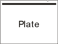 |
| Measure each of the indicated distances according to the illustration |  |
|
Where:
|
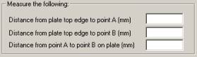
A1 = Distance from plate top edge to point A (mm) B1 = Distance from plate top edge to point B (mm) AB = Distance from point A to point B on plate (mm) |
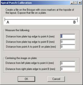
| Enter the Spiral Punch Calibration window. Insert the three measurements into the windows under "Measure the following". Entering these three values enables the Lotem to automatically correct for image skew according to the resolution. If the image was not parallel to the gripper edge, the Virtual HP App Value will change altering the depth of the spiral punch. The next two values affect image centering across the plate. |
 |
| Measure: The distance (A) from the left plate edge to the image (mm) The distance (B) from the right plate edge to the image (mm) Note: If A1 = B1 (image is square to the plate) and A = B (plate is centered), there is no need to continue the procedure. You can close all windows now. |
 |
|
Insert these values into the windows under "Centering the image on Plate "Click Apply |
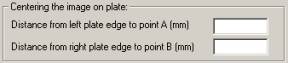 |
|
Recheck the Virtual HP App Value. If it has changed from 700 to a negative number (such as seen in this example), you must readjust the position of the course H.P. on the spiral motor and repeat the procedure. Otherwise… |
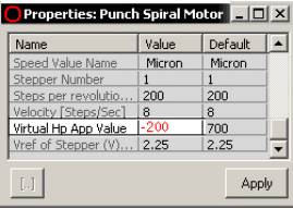 |
If the Virtual HP App Value is a positive number,
Expose the same file again.
Make sure that the image is parallel to the gripper edge and centered from side
to side. Repeat the Exposure in resolutions 60 and 140. Recheck for squareness
and centering.
If there are registration problems between resolutions, turn off the spiral punch motor. Turning off the spiral punch motor does not affect the final image quality; but saves a lot of trouble for service engineers on site. Make sure choosing the correct motor-the one that dictates the size of the bite, not the one that takes the bite. (Efraim's tip)
Side to side: Tell the plate to purposely not to go all the way into the punch pin, then you can see if you are centered side to side.
In registry: I/O Objects\ Loading System\Loading System Setup, select "X In Drum Final (mm)" - the data is normally 12, change it to 5. This parameter can be increased passing 12 to make sure the plate shoves onto the pin properly; data of "Y in Drum" can also be decreased to change the angle of the plate entering the head grippers.
How much to bite off: Effects rotation of image on plate. Get a mylar ruler to measure rotation. Run a file to see if it's centered, and check for image rotation. In GUI, Utilities\Hardware\Punch System\Spiral Punch System, right click on Punch Spiral Motor. In the Spiral Punch Calibration box, enter the requested distances (B is the Spiral punch end of leading edge).
In order to check the spiral punch, you must run the file in Brisque because in diagnostic mode (through the GUI), the spiral punch doesn't move according to resolution, it just moves to Spiral motor's "Max Pos App Value", the position when its imaging 100ppm. To check spiral punch motor movement, move the motor back to 0 position before every plate, listen and track its movement as it punches, and stack consecutive punched plates on top of each other to see if anything changed.