Applies to |
|
- Lotem™ 800 Quantum Spectrum
|
Priority = Mandatory
Release date = 05 Nov 2002
Type of change = Mandatory
|
Machines affected |
|
All machines currently in the
field. |
Component |
|
Plate conveyor
|
Problem |
|
When you unload the carrier, it should slide onto the
plate; however, it frequently does one
of the following:
-
Collides with the upper shaft of the conveyor and falls into the
unloading basket.
-
Collides with the middle shaft of the conveyor and does not
exit completely from the Lotem's unload tray.
-
Falls into the basket.
|
Solution |
|
Install the following additional parts to guide the
carrier onto the plate conveyor as it unloads:
-
Four carrier support brackets on the upper right and left corners of
the upper assembly of the plate conveyor.
-
Two middle assemblies of the plate conveyor.
|
Time needed to
implement |
|
1/2 hour |
Parts needed |
|
Part Name |
Qty |
P/N |
Carrier Support - Left |
1 |
290A9B789 |
Carrier Support - Right |
1 |
290A9B791 |
| Packing Label - Wht |
1 |
374A00080 |
| Adap, 1 to location |
2 |
280A2P161 |
| Carrier Protector - Left |
1 |
290A9C 214 |
| Carrier Protector - Right |
1 |
290A9C 213 |
| Soc Hd Cap Stst 10-32*5/16" |
4 |
380A06030 |
| FCO Document |
1 |
719-28936 |
|
Special Tools needed |
|
Set of Allan® keys |
Procedure |
|
This procedure includes the following steps:
-
Installing the carrier support brackets.
-
Installing the carrier middle support brackets.
-
Testing functionality.
Installing the carrier support brackets
- Lift the upper assembly of the plate conveyor off of the
conveyor hooks on the back of the output device and lean it
toward the conveyor as far as it will go. Let it rest in
this position while you are installing the support brackets.
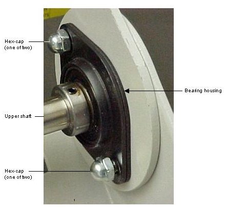
- On one side of the upper shaft of the upper assembly, remove
the two hex-caps from the bearing housing securing screws
(shown below).
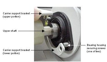
- Place the appropriate carrier support bracket onto the
bearing housing securing screws, as shown below.
Note: Make sure that the upper portion
of the bracket is toward the output device.
- Apply Loctite 242™ to the two hex-caps you previously
removed, and replace and tighten the two hex-caps.
- Repeat steps 2 and 3 on the other side.
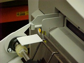
- Place the upper assembly onto the conveyor hooks on the back
of the output device. The bracket should be positioned as
shown below.
Installing the carrier middle support brackets
- In the middle of the conveyor should be two spacers. If they are
missing, add
them with the supplied screws.
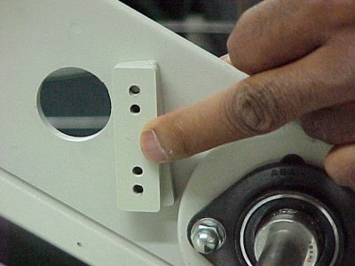
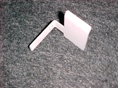
- Connect the middle support brackets to the spacers (described in step 1) with
the screws supplied.
Testing functionality
- Load and unload a carrier.
- Verify that the carrier unloads onto the plate conveyor
without colliding with the upper or middle shaft of the
plate conveyor and without falling into the unloading basket.
|
Logistics |
|
Approved quantities:
DU |
Qty |
CAM: |
|
CEU: |
|
CAP: |
|
CJP: |
|
CMA: |
|
Other: |
|
No Limit: |
|
Schedule supplies for first lots:
DU |
Month |
Qty |
Month |
Qty |
Month |
Qty |
CAM: |
|
|
|
|
|
|
CEU: |
|
|
|
|
|
|
CAP: |
|
|
|
|
|
|
CJP: |
|
|
|
|
|
|
CMA: |
|
|
|
|
|
|
Other: |
|
|
|
|
|
|
Lead Time: 1.5 months |
|
Technical
contact |
|
Nir Peleg Product Support Manager: Yaron Soffer
Approval Date: Nov 2002 |
Modified by |
|
Nir Peleg |
Date submitted |
|
25 Nov 2002
719-28936
|

